

Ein universelles Funkfernbedienungsset für Lkw- und Nutzfahrzeugwinden, die mit 12-V- oder 24-V-Gleichstromsystemen betrieben werden, ist im Jahr 2026 die praktischste und kostengünstigste Nachrüstung für jede bestehende Windenanlage. Diese Sets ersetzen gefährliche festverdrahtete Hängesteuerungen durch einen wetterfesten Handsender und einen relaisbasierten Empfänger, der direkt an den Magnetkreis der Winde angeschlossen wird. So erhalten Bediener die volle Kontrolle über das Ein- und Ausfahren aus Entfernungen von bis zu 100 Fuß, während sie sich sicher außerhalb der Seilzuglinie aufhalten können. Ein hochwertiges Universal-Kit ist mit praktisch allen gängigen Windenmarken und Leistungsklassen kompatibel und lässt sich in weniger als zwei Stunden installieren, ohne dass die werkseitige Verkabelung durchtrennt werden muss.
Sollte für Ihr Projekt der Einsatz des „Wireless Remote Kit for Truck“ erforderlich sein, können Sie sich gerne an uns wenden, um ein kostenloses Angebot zu erhalten.
Was ist ein universelles Funkfernbedienungsset für Winden und warum ist die Nennspannung von Bedeutung?
A universal wireless remote kit for truck and utility winches is a plug-and-play aftermarket control system that adds wireless handheld operation to any existing electric winch, regardless of the winch’s original manufacturer or control system design. The kit consists of two core elements: a handheld battery-powered transmitter that the operator carries, and a receiver unit that wires into the winch’s existing solenoid or contactor circuit. When the operator presses the transmit button, the receiver activates the appropriate relay output, which in turn energizes the winch solenoid to run the motor in the commanded direction.
The “universal” designation means the receiver’s relay outputs connect to the same two-wire solenoid input that the factory hardwired pendant uses, making it compatible with any winch that uses a standard solenoid pack architecture — which covers the overwhelming majority of electric truck and utility winches from Warn, Smittybilt, Superwinch, Warn, Rough Country, Mile Marker, Westin, and hundreds of smaller brands.
Voltage rating is the specification that most directly determines compatibility with a specific winch installation. The receiver unit draws its operating power from the winch’s control circuit, which is either 12V DC (the standard for consumer pickup truck and SUV winches) or 24V DC (standard on commercial vehicles, heavy utility trucks, military vehicles, and many agricultural applications). A receiver designed for 12V operation will be damaged if connected to a 24V control circuit. Many quality universal kits now include auto-detecting power supplies that accept 10-30V DC input, covering both 12V and 24V systems from a single product SKU — a significant convenience for fleet procurement where mixed-voltage vehicles are common.
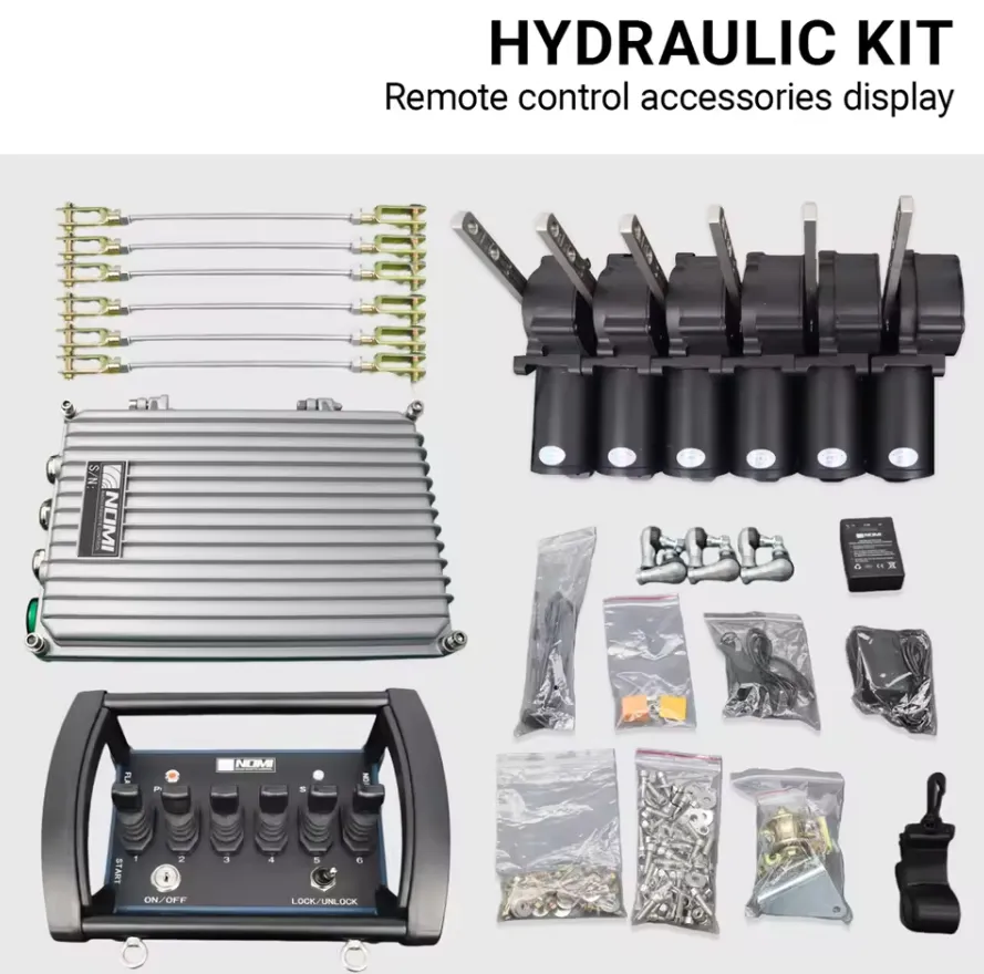
Wir haben universelle drahtlose Winden-Kits auf einer Vielzahl von Fahrzeugplattformen getestet und bewertet, darunter Halbtonnen-Pickups, Ein-Tonnen-Nutzfahrzeuge, landwirtschaftliche Traktoren, militärische LMTV-Plattformen und gewerbliche Abschleppfahrzeuge mit Pritsche. Das grundlegende Wertversprechen ist immer dasselbe: Durch den Wegfall des physischen Steuerkabels wird die häufigste Ursache für Verletzungen im Zusammenhang mit Winden beseitigt – nämlich dass der Bediener während der Bedienung eines fest verdrahteten Handbediengeräts in der Gefahrenzone der Lastleine steht.
Wie funktioniert ein kabelloses Fernbedienungsset für Universal-Winden aus elektrischer Sicht?
Die Schnittstelle für die Magnetventil-Steuerschaltung
Das Verständnis der elektrischen Schnittstelle zwischen einem universellen Funkfernbedienungsset und einem Winden-Magnetpaket ist der Ausgangspunkt für eine korrekte Installation und eine effektive Fehlerbehebung. Jede elektrische Winde verwendet ein Magnetventilpaket (auch als Schützbox bezeichnet), um den Hochstrom-Motorstromkreis zu schalten. Im Inneren des Magnetventilpakets befinden sich zwei Hochleistungsmagnetventile: eines für den Vorwärtslauf des Motors (Winde ein) und eines für den Rückwärtslauf des Motors (Winde aus). Die Magnetspulen arbeiten mit geringem Strom (typischerweise 1–3 Ampere bei 12 V oder 24 V) und werden vom Steuerkreis mit Strom versorgt – ursprünglich über die fest verdrahtete Handsteuerung.
The wireless receiver kit simply intercepts this control circuit signal. The receiver’s two relay outputs connect in parallel with the existing pendant plug connections at the solenoid pack. When the receiver activates Relay 1, it applies the control voltage to the “winch in” solenoid coil. When it activates Relay 2, it applies control voltage to the “winch out” solenoid coil. The solenoids then switch the high-current motor circuit exactly as they would under pendant control.
Signalfluss vom Drücken der Sendertaste bis zur Motorbewegung
Der gesamte elektrische Signalweg in einem funktionsfähigen kabellosen Winden-Bausatz:
Der Bediener drückt die Taste „IN“ oder „OUT“ am Sender
↓
Der Mikrocontroller des Senders codiert den Befehl mit der eindeutigen Geräte-ID
↓
Auf der Betriebsfrequenz (433 MHz, 868 MHz oder 915 MHz) gesendetes HF-Signal
↓
Die Empfangsantenne empfängt das HF-Signal
↓
Der Mikrocontroller des Empfängers decodiert das Signal und überprüft die Geräte-ID
↓
Übereinstimmende Geräte-ID: Der Empfänger aktiviert den entsprechenden Relaisausgang
↓
Der Relaiskontakt schließt sich und legt die Steuerspannung an die Magnetspule der Winde an
↓
Das Magnetventil wird erregt, wodurch der Kontakt des Hochstrom-Motorkreises geschlossen wird
↓
Der Motor läuft in die vorgegebene Richtung
↓
Der Bediener lässt die Taste los: Der Sender stellt die Übertragung ein, das Relais öffnet sich, das Magnetventil wird stromlos, der Motor stoppt
This entire sequence — from button press to motor movement — takes between 50 and 150 milliseconds in a quality system. The motor stopping sequence is equally fast: when the operator releases the button, the transmitter’s hold-to-run (dead man’s) protocol stops the command signal, the receiver drops the relay, the solenoid de-energizes, and the motor stops.
Wie der Empfänger sich mit Strom versorgt
The receiver unit requires its own low-current power supply (typically 50-200 mA at operating voltage) to power its microcontroller, RF circuitry, and relay coils. In a universal kit, this power comes from the winch’s control circuit — the same switched 12V or 24V supply that powers the solenoid coil circuit. The receiver connects its power input to the vehicle’s accessory power or the winch solenoid pack’s control power supply terminal.
Bei Installationen mit einem Netzteil mit automatischer Spannungserkennung verfügt der Empfänger über einen Schaltregler mit breitem Eingangsspannungsbereich, der jede Gleichspannung zwischen 10 V und 30 V akzeptiert und unabhängig von der Eingangsspannung eine stabile interne Betriebsspannung von 5 V oder 3,3 V liefert. Dadurch ist dieselbe physische Empfängereinheit ohne interne Modifikationen sowohl mit 12-V- als auch mit 24-V-Anlagen kompatibel.
Anforderungen an die Nennleistung von Relais
The relay outputs inside the receiver switch the solenoid coil circuit, not the motor’s main power circuit. The solenoid coil draws typically 1-3 amps at operating voltage. However, the relay must also handle the inductive switching transient when the solenoid coil de-energizes — a voltage spike that can reach 5-10 times the supply voltage in an unprotected circuit. Quality receivers include flyback diodes (also called freewheeling diodes) across each relay output to absorb this inductive transient and protect the relay contacts.
Die Nennleistung der Relaiskontakte im Empfänger sollte mindestens 10 A bei 30 V Gleichstrom betragen, um sowohl den Strom der Magnetspule als auch die induktiven Transienten mit ausreichender Reserve bewältigen zu können. Bei Empfängern mit Relaiskontakten, deren Nennleistung nur 3–5 A beträgt, kommt es durch induktives Schalten zu Kontaktverschleiß, sodass sie bereits nach wenigen hundert Schaltzyklen ausfallen.
Welche Komponenten sind in einem kompletten universellen Funkfernbedienungsset für Winden enthalten?
Standard-Lieferumfang
Ein vollständiges, fachgerecht zusammengestelltes Universal-Fernbedienungsset für Funkwinden enthält die folgenden Teile. Sets, bei denen Teile dieser Liste fehlen, sollten vor dem Kauf sorgfältig geprüft werden:
| Komponente | Standard-Spezifikation | Zweck |
|---|---|---|
| HF-Sender (Handfernbedienung) | FHSS (feste Frequenz), IP65+, Tasten mit Dauerbetrieb, dedizierter Not-Aus-Schalter | Primäre Bedienoberfläche für den Betreiber |
| HF-Empfängereinheit | Anpassungsprotokoll, IP54+, 10–30 V Eingang oder spannungsspezifisch, 2 Relaisausgänge | Decodiert Befehle des Senders, aktiviert Magnetventile |
| Befestigungsmaterial für den Empfänger | Edelstahlschrauben, Gummitüllen, Kabelbinder | Befestigen Sie den Empfänger am Fahrzeug oder an der Winde. |
| Kabelbaum | Vorkonfektioniert mit passenden Steckern, 16–18 AWG, 3–6 Fuß | Empfänger an den Steuerkreis des Magnetventils anschließen |
| Steckverbinder für Magnetventile | OEM-typische oder universelle Flach- bzw. Ringklemmen | An den vorhandenen Magnetventil-Kabelbaum anschließen |
| Senderbatterien | 2× AA-Alkalibatterien oder wiederaufladbare Batterien | Den Handsender einschalten |
| Trageband für den Sender/Handgelenkband | Nylonband, Sicherheitsverschluss | Sender während des Betriebs festhalten |
| Antenne (Empfänger) | Peitschenantenne mit SMA-Stecker, angepasst auf 433/868/915 MHz | Empfang von HF-Signalen |
| Montageanleitung | Sprachspezifisch, mit Schaltplan | Hinweise zur Installation |
| Anleitungskarte zum Koppeln/Verbinden | Kurzanleitung zum Neubinden | Referenz zur Feldneubindung |
Ergänzungen zum Premium-Set
Hochwertigere Universal-Bausätze enthalten Komponenten, die die Zuverlässigkeit, Sicherheit und einfache Montage verbessern:
| Premium-Ergänzung | Funktion | Nutzen für den Nutzer |
|---|---|---|
| Wetterfestes Empfängergehäuse | Gehäuse der Schutzklasse IP67 mit abgedichteter Kabeleinführung | Schutz bei Einsätzen im Freien und im Gelände |
| LED-Statusanzeige am Empfänger | Zeigt Stromversorgung, Signalempfang und den Status der Relaisaktivierung an | Einblick in die Diagnosefunktionen, ohne das Gehäuse zu öffnen |
| Akustischer Signalton am Empfänger | Akustische Signale bei Auslösung des Not-Aus-Schalters oder bei Signalausfall | Benachrichtigt das Personal in der Nähe über eine Änderung des Systemzustands |
| Kabelgebundene Ersatz-Hängeleuchte | Kurze, 3–6 Fuß lange, spiralförmig gewickelte Hängeleitung mit demselben Stecker | Ausweichsteuerung bei Ausfall des Funksystems |
| LED-Betriebsanzeige für das Fahrzeug | Zeigt den Stromversorgungsstatus der Steuerschaltung an | Schnelle Überprüfung der Stromversorgung |
| Klettverschluss-Holster für den Sender | Befestigt den Sender am Überrollkäfig, an der Lenksäule oder am Armaturenbrett | Praktische Aufbewahrung zwischen den Einsätzen |
| Wiederaufladbarer Sender-Akku | Li-Ionen-Akku mit USB-C-Ladeanschluss | Macht die Kosten für den Austausch von AA-Batterien überflüssig |
Welche Windenmarken und -modelle sind mit universellen Funkfernbedienungssets kompatibel?
Übersicht zur Markenverträglichkeit
Universelle Funkfernbedienungssätze sind für den Anschluss an die standardmäßige Zweidraht-Steuerschnittstelle für Magnetspulen ausgelegt, die bei praktisch allen elektrischen Lkw- und Nutzfahrzeugwinden zum Einsatz kommt. Die folgende Tabelle enthält die gängigsten Windenmarken und gibt Auskunft über deren Kompatibilität:
| Windenmarke | Gängige Modelle | Steuerspannung | Typ des Magnetventilanschlusses | Kompatibel mit Universal-Bausatz |
|---|---|---|---|---|
| Warnung | VR-Serie, XT-Serie, Zeon, M8000 | 12 V | 2-poliger Deutsch-Stecker oder Flachstecker | Ja |
| Smittybilt | X20, XRC, Comp Gen2 | 12 V | Flachstecker | Ja |
| Superwinch | Tiger Shark, S-Serie, LT-Serie | 12 V | 2-poliger Stecker | Ja |
| Rough Country | Pro-Serie, Combo-Serie | 12 V | Flachstecker | Ja |
| Westin | HDX, Platinum-Serie | 12 V | Flachstecker | Ja |
| Meilenstein | HI/LO, Hydraulik-Serie | 12 V (elektrisch) | Flachstecker | Ja (Elektrofahrzeuge) |
| Comeup | Dichtung, DV-Serie | 12 V | 2-poliger Stecker | Ja |
| Badlands | Apex, Standard | 12 V | Flachstecker | Ja |
| Runva | EWB-Serie, EWX-Serie | 12 V oder 24 V | Flachstecker | Ja |
| VehicleX | Pro-Serie | 12 V | Flachstecker | Ja |
| Ramsey | REP-Serie, Patriot | 12 V oder 24 V | 2-poliger Stecker | Ja |
| Warn (Hochleistungsausführung) | HS9500i, ZEON Platinum | 12 V | Warn-eigene | Modellspezifischen Adapter prüfen |
| 24-V-LKW-Winde für den gewerblichen Einsatz | Verschiedene Flottenmarken | 24 V | Hochleistungs-Flachstecker oder DIN | Ja (24-V-Bausatz erforderlich) |
Situationen, in denen die universelle Kompatibilität überprüft werden muss
Zwar ist die Zweidraht-Magnetventil-Schnittstelle nahezu universell einsetzbar, doch bei einer kleinen Anzahl von Windenkonfigurationen ist eine zusätzliche Überprüfung erforderlich, bevor davon ausgegangen werden kann, dass ein Standard-Bausatz funktioniert:
Winden mit bereits eingebauter Funkverbindung: Some newer winch models (particularly from Warn’s upper product lines) include factory wireless systems with proprietary encrypted protocols. Adding a universal kit in parallel will work electrically, but may create confusion if both wireless systems are active simultaneously.
Hydraulische Winden: Universelle Funksteuerungssätze für elektrische Winden können hydraulische Winden nicht direkt steuern, da diese anstelle von Ein-/Aus-Motorschützen proportionale Magnetventile verwenden. Für die Funksteuerung von hydraulischen Winden sind Empfänger mit proportionalem Ausgang erforderlich.
Dreiphasen-Wechselstromwinden: Größere gewerbliche Seilwinden mit Drehstrommotoren und Frequenzumrichtern erfordern industrielle Funksysteme und keine handelsüblichen 12-V-/24-V-Universal-Sets.
Winden mit Moment- bzw. Dauermagnetventilen: Die meisten Winden verwenden Momentmagnetventile (die ständig mit Strom versorgt werden müssen, um aktiv zu bleiben), was dem „Hold-to-Run“-Verhalten von handelsüblichen Funk-Bausätzen entspricht. Bei einigen wenigen älteren Windenmodellen kommen selbsthaltende oder verriegelnde Magnetventile zum Einsatz – überprüfen Sie den Magnetventiltyp, bevor Sie sich für einen Bausatz entscheiden.
Wie montiert man ein universelles Funkfernbedienungsset an einer 12-V- oder 24-V-Winde?
Vorbereitungen vor der Installation
Bevor Sie mit der Installation beginnen, sollten Sie die folgenden Informationen und Materialien bereithalten:
- Confirm the winch’s control circuit voltage (12V or 24V) by checking the winch nameplate or vehicle electrical specification.
- Suchen Sie das Magnetventilmodul an der Winde und identifizieren Sie die beiden Anschlüsse für die Steuerkabel, an die der werkseitige Handbedienungsschalter angeschlossen wird.
- Wählen Sie einen Montageort für die Empfängereinheit aus: nach Möglichkeit vor direktem Spritzwasser geschützt, mit vertikal ausgerichteter Antenne für eine Rundstrahlabdeckung und in Kabelreichweite des Anschlusses für die Magnetventilsteuerung.
- Stellen Sie sicher, dass am Einbauort des Empfängers eine Steuerstromquelle verfügbar ist (geschaltete 12-V- oder 24-V-Stromversorgung, abgesicherter Stromkreis mit mindestens 3 A).
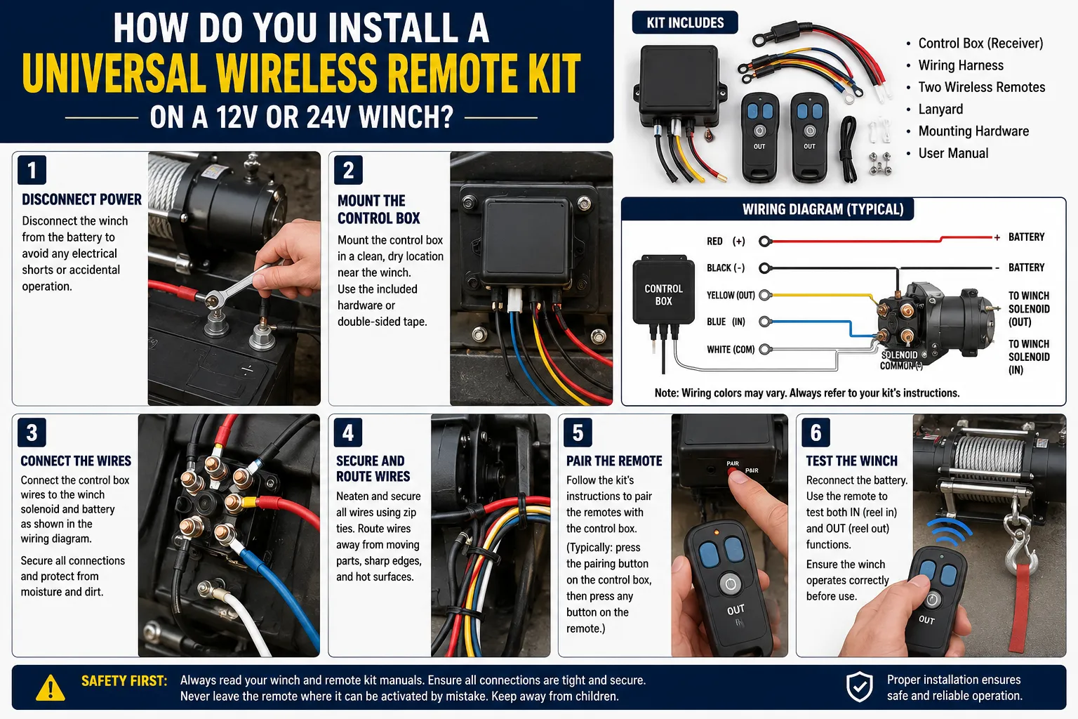
Schritt-für-Schritt-Anleitung zur Installation
Schritt 1: Fahrzeugstrom abschalten
Before making any electrical connections, disconnect the vehicle battery’s negative terminal or engage the main power disconnect switch. This prevents accidental winch activation during installation, which is a documented cause of serious injury.
Schritt 2: Anschlüsse der Magnetventilsteuerung ausfindig machen und darauf zugreifen
On most winches, the factory pendant plugs into a two-wire connector on the solenoid pack’s control harness. This connector typically uses Deutsch DT-series, weatherproof blade, or simple spade terminal connections. Identify:
- The “winch in” control wire (typically labeled IN, +, or colored green on OEM harnesses)
- The “winch out” control wire (typically labeled OUT, -, or colored red or white on OEM harnesses)
- Die Erdungsleitung oder die Rückleitung des Steuerkreises.
Schritt 3: Anschließen der Ausgangskabel des Empfängers
Connect the receiver’s two relay output wires to the solenoid control circuit using the kit’s provided connectors:
| Empfängerkabel | Anschlusspunkt | Anmerkungen |
|---|---|---|
| Ausgang von Relais 1 (IN) | Steuereingang des Windenmagnetventils IN | Überprüfen Sie die Polarität, wenn das Magnetventil polaritätsempfindlich ist. |
| Ausgang (OUT) von Relais 2 | Steuereingang „OUT“ des Windenmagnetventils | Überprüfen Sie die Polarität, wenn das Magnetventil polaritätsempfindlich ist. |
| Gemeinsame Basis | Fahrzeugchassis oder Masseanschluss für Magnetventile | Muss die Massebezugspunkt mit dem Magnetpaket teilen |
Schritt 4: Stromversorgung des Empfängers anschließen
Connect the receiver’s power input wires to the vehicle’s control circuit power supply. The positive wire connects to the switched 12V or 24V supply (use the same circuit that powers the solenoid pack, after any inline fuse). The negative wire connects to the vehicle chassis ground near the receiver mounting point.
Schritt 5: Den Empfänger montieren
Befestigen Sie die Empfängereinheit mit dem mitgelieferten Befestigungsmaterial. Wichtige Hinweise zur Montage:
- Befestigen Sie die Antenne außerhalb eines Metallgehäuses, wobei die Antennenspitze nach oben zeigen muss.
- Verwenden Sie an allen Kabeleinführungen Gummitüllen, um Scheuerschäden zu vermeiden.
- Stellen Sie sicher, dass der Empfänger an der Montageposition keinem stehenden Wasser ausgesetzt ist.
- Keep the receiver at least 150mm away from the winch motor to reduce RF interference from the motor’s brush arcing.
Schritt 6: Den Sender mit dem Empfänger koppeln
Jedes universelle Funk-Set erfordert einen anfänglichen Kopplungsvorgang, um den Sender mit dem Empfänger zu verbinden. Die Standardvorgehensweise:
- Schalten Sie den Empfänger ein (schließen Sie die Fahrzeugbatterie an).
- Press and hold the receiver’s LEARN or PAIR button for 3-5 seconds until the status LED flashes rapidly.
- Drücken Sie am Sender einmal eine beliebige Bewegungstaste.
- Die Status-LED des Empfängers beginnt langsam zu blinken oder leuchtet dauerhaft, was die erfolgreiche Kopplung bestätigt.
- Testen Sie sowohl die IN- als auch die OUT-Funktion, um die korrekte Richtungsfunktion zu überprüfen.
Schritt 7: Überprüfung und Korrektur der Ausrichtung
If the transmitter’s IN button causes the winch to pay out rope (wrong direction), swap the receiver’s two relay output connections at the solenoid. This reversal corrects directional mapping without any reprogramming.
Schritt 8: Wiederanschluss der Fahrzeugstromversorgung und vollständiger Funktionstest
Schließen Sie den Minuspol der Batterie wieder an. Testen Sie die Funkfernbedienung über den gesamten Betriebsbereich, überprüfen Sie die Not-Aus-Funktion (sofern das Set über diese Funktion verfügt) und vergewissern Sie sich, dass das vorhandene werkseitige Handbediengerät weiterhin funktioniert, wenn es angeschlossen ist (für die Dual-Steuerungsfunktion).
Häufige Installationsfehler und deren Behebung
| Fehler | Symptom | Korrektur |
|---|---|---|
| Empfänger, der an den 12-V-Stromkreis einer 24-V-Winde angeschlossen ist | Der Empfänger lässt sich einschalten, aber die Relais geben Störgeräusche von sich oder arbeiten unregelmäßig | Durch einen für 24 V ausgelegten oder einen Empfänger mit automatischer Spannungserkennung ersetzen |
| Antenne, die im Metallstoßfänger montiert ist | Sehr kurze Reichweite (unter 5 Fuß) | Antenne an einen externen Standort verlegen |
| Vertauschte Relaisausgangsanschlüsse | Mit der Taste „IN“ wird das Seil ausgegeben, mit der Taste „OUT“ wird es aufgerollt | Vertauschen Sie die beiden Anschlüsse der Relaisausgänge. |
| Die Masse ist mit der Karosserie statt mit dem Fahrgestell verbunden | Zeitweise Auslösung des Relais, insbesondere unter Last | Masseanschluss an den Rahmen oder den Minuspol der Batterie verlegen |
| Kein Rückschlagstromschutz an den Relaisausgängen | Plötzlicher Ausfall eines Relaiskontakts | Schließen Sie an jeden Eingang der Magnetspule eine 1N4007-Diode an, wobei die Kathode an den Pluspol angeschlossen wird. |
Welche Funkfrequenztechnologie bietet die beste Reichweite und Zuverlässigkeit?
In Universal-Kits verfügbare Technologieoptionen
Universelle Funkfernbedienungssätze für Winden nutzen drei unterschiedliche Funktechnologien, die jeweils unterschiedliche Leistungsmerkmale und Vor- und Nachteile aufweisen:
Festfrequenz 433 MHz (Basis):
Die einfachste und kostengünstigste Technologie. Sender und Empfänger arbeiten auf einem einzigen festen Kanal innerhalb des 433-MHz-ISM-Bands. Die Reichweite beträgt unter idealen Bedingungen in der Regel 30–60 Fuß. Störungen durch andere 433-MHz-Geräte (Garagentoröffner, Reifendrucksensoren, schlüssellose Zugangssysteme) können zu zeitweiligen Befehlsausfällen oder Fehlauslösungen führen. Am besten geeignet für einfache Anwendungen, bei denen sich der Bediener stets in unmittelbarer Nähe der Winde befindet und HF-Störquellen minimal sind.
Festfrequenz 315 MHz (Nordamerika, ältere Modelle):
Ein älterer Standard, der noch in einigen auf nordamerikanischen Märkten verkauften Bausätzen zu finden ist. Ähnliche Reichweiten- und Störeffekte wie bei 433 MHz. Wird im Zuge der Weiterentwicklung der behördlichen Frequenzzuweisungen zugunsten von 433 MHz und höherfrequenten Optionen schrittweise ausgemustert.
Frequenzsprung-Spreizspektrum (FHSS) bei 433 MHz / 868 MHz / 915 MHz:
Die empfohlene Technologie für alle anspruchsvollen Lkw- oder Nutzfahrzeuganwendungen. FHSS wechselt die Betriebsfrequenz hunderte Male pro Sekunde unter Verwendung einer pseudozufälligen Sequenz, die zwischen Sender und Empfänger synchronisiert ist. Dadurch ist das System praktisch immun gegen Störungen durch Geräte mit fester Frequenz sowie durch andere FHSS-Systeme, die andere Frequenzsprungsequenzen verwenden. Die Reichweite beträgt je nach konkreter Umsetzung und Umgebungsbedingungen 100 bis 300 Fuß.
Einhaltung der Frequenzbandvorschriften nach Region
| Region | Zugelassene Frequenzbänder | Aufsichtsbehörde | Erforderliche Zertifizierung |
|---|---|---|---|
| Vereinigte Staaten | 315 MHz, 433 MHz, 902–928 MHz | FCC | FCC Teil 15 (ID erforderlich) |
| Kanada | 433 MHz, 902–928 MHz | ISED | RSS-210 |
| Europäische Union | 433,05–434,79 MHz, 868,0–868,6 MHz | ETSI | CE-Richtlinie 2014/53/EU |
| Vereinigtes Königreich | 433 MHz, 868 MHz | Ofcom | UKCA |
| Australien | 433 MHz, 915–928 MHz | ACMA | RCM |
| Japan | 426 MHz, 429 MHz | MIC | TELEC |
| China | 433 MHz, 470–510 MHz | MIIT | SRRC |
Vergewissern Sie sich stets, dass das von Ihnen erworbene Set das in Ihrem Land vorgeschriebene Zertifizierungszeichen trägt. Der Betrieb eines nicht zertifizierten Funkgeräts ist in nahezu allen Rechtsordnungen verboten und kann zu Geldstrafen und zur Beschlagnahmung des Geräts führen.
Reichweitenprognosen unter realen Bedingungen
Manufacturers’ stated range figures are measured under ideal open-field conditions: transmitter and receiver at equal height, no RF interference, no physical obstructions. Real-world range in truck and utility applications is consistently lower:
| Umwelt | Typische Reichweitenverringerung unter realen Bedingungen | Angepasste Reichweite (System mit 100 m Nennreichweite) |
|---|---|---|
| Freies Gelände, keine Hindernisse | 0% | 100 m |
| Straße in einem Vorort, geparkte Fahrzeuge in der Nähe | 20-30% | 70–80 m |
| Städtische Umgebung, dichte Bebauung | 40-60% | 40–60 m |
| Im Inneren eines Gebäudes mit Metallrahmen | 50-70% | 30–50 m |
| Dichter Wald oder Dschungel | 30-50% | 50–70 m |
| Fahrzeug zwischen Sender und Empfänger | 40-60% | 40–60 m |
| Antenne, die im Metallstoßfänger montiert ist | 80-90% | 10–20 m |
Für die meisten Anwendungen von Lkw- und Nutzfahrzeugwinden ist eine Reichweite von 30–50 Fuß (10–15 Meter) aus betrieblicher Sicht ausreichend, da der Bediener jederzeit Sichtkontakt zum Seil und zur Last halten muss. Bei Einsatzfahrzeugen gewinnt die Reichweite an Bedeutung, da der Bediener die Winde unter Umständen von der gegenüberliegenden Seite eines großen Fahrzeugs oder von einer Position hinter einer physischen Barriere aus steuern muss.
Welche Sicherheitsmerkmale muss ein hochwertiges Universal-Windenfernbedienungsset aufweisen?
Unabdingbare Sicherheitsanforderungen
Die Sicherheitsarchitektur eines drahtlosen Fernbedienungssets für Winden entscheidet direkt darüber, ob es die Bediener im praktischen Einsatz schützt oder lediglich den Komfort einer drahtlosen Bedienung ohne entsprechende Sicherheitsvorteile bietet. Diese Merkmale sind für jede ernstzunehmende Anwendung unverzichtbar:
Hold-to-Run (Dead Man’s Control):
Alle Bewegungstasten müssen kontinuierlich gedrückt gehalten werden, um den Betrieb der Winde aufrechtzuerhalten. Sobald der Bediener die Taste loslässt, stoppt die Winde. Dies ist die wichtigste Sicherheitsfunktion überhaupt, da dadurch jede Ablenkung, das Herunterfallen des Senders oder ein Bewusstseinsverlust die Winde sofort zum Stillstand bringt. Ein Bausatz mit Kippschalter (Rastfunktion), bei dem die Winde nach dem Loslassen der Taste weiterläuft, darf nicht bei Anwendungen eingesetzt werden, bei denen sich das Seil in der Nähe von Personen befindet.
Spezielle Not-Aus-Taste:
Ein separater, deutlich gekennzeichneter Not-Aus-Schalter, der alle Relaisausgänge sofort abschaltet und weitere Bewegungsbefehle sperrt, bis er bewusst zurückgesetzt wird. Der Not-Aus-Schalter sollte sich in Größe, Farbe (in der Regel rot) und Anordnung deutlich von den Bewegungsschaltern unterscheiden, damit er auch ohne visuelle Bestätigung betätigt werden kann.
Watchdog-Timeout:
Verliert der Empfänger das Sendersignal für länger als eine voreingestellte Zeitüberschreitung (in der Regel 0,5–2 Sekunden), muss er automatisch beide Relaisausgänge abschalten und die Winde anhalten. Dadurch wird verhindert, dass die Batterie des Senders leer wird oder der Sender während des Betriebs der Winde aus dem Empfangsbereich gerät.
Einmalige Gerätekopplung:
Der Sender muss sich dem Empfänger mittels eines eindeutigen digitalen Codes identifizieren. Andernfalls könnte jeder kompatible Sender innerhalb der Reichweite die Winde steuern, was an Standorten mit mehreren Fahrzeugen eine erhebliche Gefahr durch unbeabsichtigte Auslösung darstellen würde.
Warnung bei niedrigem Akkustand:
Der Sender muss eine akustische und/oder optische Warnung auslösen, sobald die Batteriespannung unter den Schwellenwert fällt, ab dem eine zuverlässige HF-Übertragung gewährleistet ist, und zwar mit ausreichender Vorwarnzeit, damit der aktuelle Vorgang abgeschlossen und die Batterien vor dem Abschalten ausgetauscht werden können.
Vergleich der Sicherheitsmerkmale in den verschiedenen Qualitätsstufen der Bausätze
| Sicherheitsfunktion | Budget-Set | Mittelklasse-Set | Profi-Set |
|---|---|---|---|
| Hold-to-Run-Steuerung | Ja | Ja | Ja |
| Spezielle Not-Aus-Taste | Nein | Ja | Ja (Pilzkopf) |
| Watchdog-Timeout | 2–5 Sekunden | 1–2 Sekunden | 0,5–1 Sekunde (einstellbar) |
| Eindeutiger Kopplungscode | 8 Bit (256 Codes) | 16 Bit (65.536 Codes) | 32-Bit (über 4 Milliarden Codes) |
| Warnung bei niedrigem Akkustand | Nur LED | LED + Summer | LED + Summer + Sender-Sperre |
| Richtungsverriegelung | Nein | Manchmal | Ja (verhindert gleichzeitiges IN+OUT) |
| LED für den Empfängerstatus | Einfarbig | Mehrfarbig | Mehrfarbig + LCD |
| IP-Schutzklasse (Sender) | IP54 | IP65 | IP67 |
| IP-Schutzklasse (Empfänger) | IP54 | IP65 | IP67 |
| FCC-/CE-Zertifizierung | Selbsternannt | Zertifiziert | Mit Unterlagen zertifiziert |
Die Richtungsverriegelung: Warum sie wichtig ist
Ein hochwertiger Empfänger verfügt über eine elektronische Verriegelung, die physisch verhindert, dass beide Relaisausgänge gleichzeitig aktiv sind. Wenn sowohl das IN- als auch das OUT-Relais gleichzeitig schließen würden, würden beide Windenmagnetventile gleichzeitig erregt, was zu einem Kurzschluss im Magnetventilblock führen würde, der die Magnetventilspulen durchbrennen und die Schaltkreise der Motorschütze beschädigen könnte. Diese Verriegelung muss in der Hardware (Verdrahtung der Relaiskontakte) und nicht nur in der Software implementiert sein, um sicherzustellen, dass sie auch dann funktioniert, wenn im Mikrocontroller des Empfängers ein Firmware-Fehler auftritt.
Worin unterscheiden sich 12-V- und 24-V-Windenanlagen und was bedeutet das für die Auswahl eines Fernbedienungssets?
Unterschiede in der elektrischen Architektur
The voltage difference between 12V and 24V winch systems reflects the host vehicle’s electrical architecture and has cascading effects on current levels, cable sizing, component specifications, and remote kit selection:
| Spezifikation | 12-V-System | 24-V-System |
|---|---|---|
| Typischer Fahrzeugtyp | Pkw, SUV, leichte Nutzfahrzeuge | Nutzfahrzeuge, Schwerlastfahrzeuge, Militärfahrzeuge, landwirtschaftliche Fahrzeuge |
| Spannung des Windenmotors | 12 V Gleichstrom | 24 V Gleichstrom |
| Spitzenstrom des Motors (9.500 lb Winde) | 380–450 A | 190–225 A |
| Strom in der Magnetspule | 1-2A | 0,5–1 A |
| Querschnitt des Stromkabels (Hauptstromkreis) | 2/0–4/0 AWG | 1/0–2/0 AWG |
| Empfindlichkeit gegenüber Spannungsabfall | Hoch (größerer Abfall pro Widerstandseinheit) | Niedriger (geringerer Abfall pro Widerstandseinheit) |
| Batteriesystem | Eine einzelne 12-V-Batterie oder zwei parallel geschaltete 12-V-Batterien | Zwei 12-V-Batterien in Reihe geschaltet (Nennspannung 24 V) |
| Leistung der Lichtmaschine | 12 V, 130–270 A | 24 V, 70–150 A |
Warum 24-V-Systeme praktische Vorteile bieten
Bei gleicher Ausgangsleistung nimmt ein 24-V-System nur halb so viel Strom auf wie ein 12-V-System. Dieser um die Hälfte reduzierte Strombedarf bedeutet:
- Es können Stromkabel mit kleinerem Durchmesser verwendet werden, wobei der Spannungsabfall gleich bleibt.
- Die Kontakte von Magnetventilen und Relais erwärmen sich weniger, da die I²R-Erwärmung bei gleicher Leistungsaufnahme durch 75% reduziert wird.
- Der Spannungsabfall an Steckverbindern und entlang der Kabelstrecken führt zu einem geringeren Leistungsverlust.
- Der Windenmotor wird bei starken Zugkräften gleichmäßiger mit Spannung versorgt, wodurch das Drehmoment aufrechterhalten wird, auch wenn die Batteriespannung unter Last abfällt.
For fleet operators managing large numbers of utility trucks, the 24V system’s reduced cable complexity and improved voltage regulation under load are meaningful operational advantages.
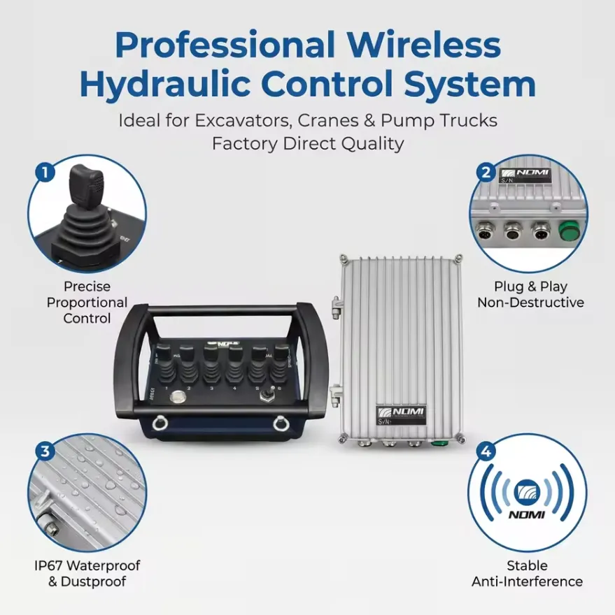
Empfänger mit automatischer Erkennung: Die universelle Lösung für gemischte Fuhrparks
Flottenbeschaffungsmanager, die für gemischte 12-V-/24-V-Fahrzeugflotten verantwortlich sind, stehen bei drahtlosen Winden-Bausätzen vor einer Herausforderung: Sie müssen zwei separate Artikelnummern für dasselbe funktional identische Produkt führen. Empfänger mit automatischer Erkennung lösen dieses Problem durch den Einbau eines Schaltnetzteils mit breitem Eingangsbereich, das jede Gleichstrom-Eingangsspannung zwischen 10 V und 30 V automatisch erkennt und reguliert. Ein einziges Empfängermodell deckt beide Systemspannungen ab, ohne dass Änderungen oder Neukonfigurationen erforderlich sind.
The auto-sensing feature also provides protection against transient voltage spikes common in commercial vehicle electrical systems. During engine cranking, the vehicle’s electrical system voltage drops briefly below 10V; during load dump events (sudden disconnection of a large inductive load), voltage can spike above 30V. A wide-input regulated receiver handles both extremes without damage.
Wie schneiden universelle Funkfernbedienungssätze im Vergleich zu OEM-Fernbedienungssystemen für Seilwinden ab?
Direkter Vergleich
| Vergleichsfaktor | Universelles WLAN-Set | OEM-/Werks-Funkfernbedienung |
|---|---|---|
| Anschaffungskosten | $30-$150 | $80–$350 (oft separat erhältlich) |
| Kompatibilität mit Seilwinden | Zahlreiche Marken und Modelle | Marken- bzw. modellspezifisch |
| Verfügbarkeit von Ersatzteilen | Weit verbreitet, zahlreiche Anbieter | Nur für Erstausrüster, wird möglicherweise nicht mehr angeboten |
| Komplexität der Installation | Mittel (Verkabelung erforderlich) | Niedrig (Steckverbindung) |
| Signalprotokoll | Standardisiert oder FHSS | Proprietäre Verschlüsselung (bessere Sicherheit) |
| Tiefe der Funktion | Grundausstattung EIN/AUS + Not-Aus | Umfasst manchmal eine Drehzahlregelung und Diagnosefunktionen |
| Reichweite | 30–300 Fuß (produktabhängig) | 50–150 Fuß (die meisten Originalfernbedienungen) |
| Haltbarkeit | IP54–IP67 (produktabhängig) | IP54–IP65 (die meisten OEM-Geräte) |
| Flexibilität bei der Paarung | Mehrere Sender können gekoppelt werden | Oft auf werkseitig gekoppelte Geräte beschränkt |
| Störfestigkeit | FHSS-Modelle: hervorragend | Hängt von der jeweiligen OEM-Implementierung ab |
| Rechtliche Auswirkungen/Auswirkungen auf die Gewährleistung | Kann die Garantie für die Winde beeinträchtigen | Keine Auswirkungen auf die Gewährleistung |
Wenn Universal-Kits die OEM-Systeme übertreffen
Universal-Kits bieten in drei konkreten Fällen ein besseres Preis-Leistungs-Verhältnis:
Modernisierung älterer Winden: When an existing winch’s factory remote system is discontinued, damaged, or simply not available in the replacement market, a universal kit provides full wireless functionality at a fraction of the cost of replacing the entire winch. We have seen numerous cases where a quality universal kit extended a perfectly functional winch’s service life by 5-10 years.
Standardisierung von Mehrmarkenflotten: Ein Flottenbetreiber, der drei verschiedene Windenmarken in 40 Fahrzeugen einsetzt, kann auf ein einziges universelles Modell eines Funk-Kits umstellen und so die Ersatzteilbestände, die Schulung der Bediener und die Wartungsabläufe vereinfachen. Der Versuch, Original-Ersatzteile von drei verschiedenen Herstellern vorrätig zu halten, führt zu erheblichen Komplexitäten bei der Beschaffung.
Erweiterte Anforderungen an die Reichweite: Mehrere auf dem Markt erhältliche universelle FHSS-Bausätze bieten eine größere effektive Reichweite als die Original-Handsender, die sie ersetzen, da sie eine ausgereiftere Funktechnologie nutzen als viele werkseitige Funksysteme.
Was sind die wichtigsten Spezifikationen, die man vor dem Kauf eines Universal-Windenfernbedienungssets prüfen sollte?
The Buyer’s Specification Checklist
| Spezifikation | Was ist zu prüfen? | Mindestwert |
|---|---|---|
| Eingangsspannungsbereich | Automatische Erkennung oder spannungsspezifisch | Muss zum Bordnetz Ihres Fahrzeugs passen (12 V oder 24 V) |
| Nennstrom des Relaisausgangs | Strombelastbarkeit der Relaiskontakte | Mindestens 10 A bei Systemspannung |
| Drahtlose Technologie | Feste Frequenz oder FHSS | FHSS wird dringend bevorzugt |
| Einsatzbereich | Manufacturer’s stated range | Mindestens 30 m für den Standardgebrauch |
| Schutzart des Senders | IP-Schutzart am Gehäuse | Mindestens IP65 für den Einsatz im Freien/im Gelände |
| IP-Schutzklasse des Empfängers | IP-Schutzart am Gehäuse | Mindestens Schutzart IP65 für die Montage im Außenbereich |
| Betriebstemperatur | Min.-/Max.-Temperaturbereich | mindestens -20 °C bis +70 °C |
| Hold-to-Run-Steuerung | Verhalten der Schaltfläche | Muss durch Gedrückthalten betätigt werden; keine Tasten mit Rastfunktion |
| Not-Aus-Funktion | Spezielle Not-Aus-Taste | Erforderlich für jede Antragstellung im Zusammenhang mit dem Lastlinienrisiko |
| Watchdog-Timeout | Reaktionszeit bei Signalausfall | Weniger als 2 Sekunden |
| Behördliche Zertifizierung | FCC-, CE- und RoHS-Kennzeichnungen | Matching your country’s requirement |
| Länge des Paarungscodes | Anzahl der Bits der eindeutigen ID | Mindestens 16 Bit für Standorte mit einem Rechner; 32 Bit für Standorte mit mehreren Rechnern |
| Akkulaufzeit | Betriebsstunden pro Satz | Über 40 Stunden bei AA-Alkalibatterien |
| Garantiezeitraum | Herstellergarantie | Mindestens 12 Monate |
| Verfügbarkeit von Ersatzsendern | Können zusätzliche Sender erworben werden? | Muss separat erhältlich sein |
Referenzmatrix für das Preis-Leistungs-Verhältnis
| Preisspanne (USD) | Typisches Qualitätsniveau | Wesentliche Einschränkungen | Beste Bewerbung |
|---|---|---|---|
| $25-$60 | Budget | Feste Frequenz, Schutzart IP54, kurze Reichweite, kein Not-Aus | Leichte, gelegentliche Nutzung, kontrollierte Umgebung |
| $60-$120 | Mittelklasse | FHSS oder „Improved Fixed“, IP65, Not-Aus, Reichweite 50–100 m | Normale Geländefahrt, Nutzfahrzeug, regelmäßiger Einsatz |
| $120-$200 | Professionell | FHSS, IP67, einstellbarer Watchdog, umfassende Sicherheitsfunktionen, Reichweite 100–300 m | Gewerblicher Fuhrpark, täglicher Einsatz, Gefahrenbereich |
| $200+ | Industrie | FHSS-verschlüsselt, Schutzart IP68, Sicherheitsklasse PLc, umfassende Dokumentation | Kritische Infrastruktur, Schwerlastverkehr |
Welche Wartungs- und Fehlerbehebungsmaßnahmen sorgen dafür, dass Ihr kabelloses Winden-Set zuverlässig funktioniert?
Plan für vorbeugende Wartungsmaßnahmen
| Intervall | Aufgabe | Werkzeuge/Materialien |
|---|---|---|
| Vor jedem Gebrauch | IN- und OUT-Funktionen prüfen; Batterieanzeige des Senders überprüfen; Sendergehäuse auf Risse untersuchen | Sichtprüfung |
| Monatlich | Reinigen Sie die Empfängerantenne mit einem trockenen Tuch; überprüfen Sie die Kabelverbindungen auf Abrieb; vergewissern Sie sich, dass die Befestigungselemente des Empfängers fest sitzen | Drehmomentschlüssel, Reinigungstuch |
| Vierteljährlich | Relaisausgänge am Magnetventil auf Korrosion prüfen; den gesamten Betriebsbereich testen; den Zustand der Dichtungen an Sender und Empfänger überprüfen | Dielektrisches Fett, Kontaktreiniger |
| Jährlich | Die Batterien des Messumformers unabhängig vom Status der Anzeige austauschen; die Relaiskontakte mit einem Multimeter prüfen; die Not-Aus-Funktion und die Watchdog-Zeitüberschreitung testen | Multimeter, Ersatzbatterien |
| Nach einem Überflutungsereignis | Dichtungen des Empfängergehäuses prüfen; Sender trocknen; Funktionsprüfung vor der Wiederinbetriebnahme durchführen | Sauberes, trockenes Tuch, Sichtprüfung |
Systematische Fehlerbehebung: Fehler-für-Fehler-Diagnose
| Symptom | Wahrscheinlichste Ursache | Diagnoseschritt | Beschluss |
|---|---|---|---|
| Keine Reaktion auf irgendeine Schaltfläche | Leere Senderbatterie | Batteriespannung messen (sollte bei 4×AA über 4,5 V liegen) | Batterien austauschen |
| Keine Reaktion, neue Batterien | Sender-Empfänger-Kopplung unterbrochen | LED-Status des Empfängers prüfen; Neuzuordnung versuchen | Sender gemäß den Anweisungen des Herstellers neu zuordnen |
| Sehr kurze Reichweite (unter 3 Meter) | Antenne, die im Metall montiert ist | Überprüfen Sie die Position der Antenne visuell | Antenne an einen externen Standort verlegen |
| Unregelmäßige Reaktion | Schwache Batterie oder HF-Störungen | Test aus nächster Nähe durchführen; Batterien austauschen; auf Störquellen prüfen | Batterien austauschen; bei Geräten mit fester Frequenz auf eine weniger ausgelastete Frequenz umstellen |
| Die Winde läuft in die falsche Richtung | Die Leitungen des Relaisausgangs wurden vertauscht | Vergleichen Sie die Verkabelung mit dem Schaltplan | Vertauschen Sie die beiden Anschlüsse der Relaisausgänge. |
| Beide Richtungen laufen gleichzeitig | Ausfall der Richtungssperre | Relaisausgangsverkabelung auf Kurzschluss prüfen | Überprüfen Sie die korrekte Verkabelung; tauschen Sie den Empfänger aus, wenn die Verriegelung einen internen Fehler aufweist. |
| Die Winde läuft, ohne dass eine Taste gedrückt wird | Durch HF-Störungen ausgelöstes Relais | Auf Geräte im 433-MHz-Bereich in der Nähe prüfen | Wechseln Sie zum FHSS-Kit oder stellen Sie den Empfänger weiter entfernt von der Störquelle auf. |
| Der Empfänger schaltet sich willkürlich aus | Spannungsabfall in der Stromversorgung unter Last der Winde | Die Versorgungsspannung des Empfängers während des Windenbetriebs messen | Kondensator an die Stromversorgung des Empfängers anschließen; die Verlegung des Netzkabels verbessern |
| Der Not-Aus-Schalter stoppt die Winde nicht | Not-Aus-Schalter nicht an den Sicherheitskreis angeschlossen | Verkabelung des Not-Aus-Stromkreises überprüfen | Die Verkabelung gemäß der Anleitung des Bausatzes vornehmen; einen fest verdrahteten Not-Aus-Schalter hinzufügen, falls dieser im Bausatz fehlt |
In welchen Branchen und für welche Fahrzeugtypen werden universelle Funkfernbedienungssätze für Seilwinden eingesetzt?
Anwendungsbereitstellung nach Branchen
| Branche / Anwendung | Fahrzeugtyp | Spannung des Windensystems | Anforderungen an das Fernbedienungsset |
|---|---|---|---|
| Freizeitaktivitäten im Gelände | Pickup, SUV | 12 V | IP67, FHSS, kompakter Sender |
| Landwirtschaft / Bauernhof | Traktor, ATV, UTV | 12 V oder 24 V | Automatische Spannungserkennung, robustes Gehäuse |
| Versorgungs- und Telekommunikationsbranche | Nutzfahrzeug, Transporter | 12 V oder 24 V | Tasten mit großer Reichweite, die auch mit Handschuhen bedient werden können |
| Forstwirtschaft und Holz | Rückezug, Ackerschlepper | 24 V | IP67, Kälteschutzklasse, große Reichweite |
| Bauwesen | Pritschenwagen, Kranwagen | 12 V oder 24 V | FHSS, Not-Aus, professionelle Qualität |
| Militär und Verteidigung | LMTV, HMMWV, JLTV | 24 V | Automatische Erkennung, verschlüsselte Kopplung, robust |
| Suche und Rettung | Rettungswagen, Allradantrieb | 12 V | IP67, handschuhfreundlich, zuverlässiger Not-Aus-Schalter |
| Meeres- / Küstenbereich | Arbeitsboot, Hafenstapler | 12 V | IP68, Edelstahlbeschläge, korrosionsbeständig |
| Abschleppen und Bergung | Schwerlast-Abschleppwagen, Rollback | 12 V oder 24 V | Große Reichweite, Unterstützung mehrerer Sender |
| Tagebaufläche | Service-Lkw, Leichtfahrzeug | 24 V | FHSS, IP67, funkenfreie Kontakte |
| Kommunale Dienstleistungen | Service-Lkw, Schneepflug | 12 V oder 24 V | Automatische Erkennung, Leistung bei kalten Temperaturen |
Warum Nutzfahrzeuge am meisten von universellen WLAN-Kits profitieren
Nutzfahrzeuge, die von Telekommunikationsteams, Stromversorgern und kommunalen Dienststellen eingesetzt werden, bieten die überzeugendsten betrieblichen Argumente für universelle drahtlose Winden-Fernbedienungssätze. Diese Fahrzeuge nutzen ihre Winden während der gesamten Schicht ununterbrochen – zum Ziehen von Kabeltrommeln, zum Positionieren von Geräten und zum Bergen festgefahrener Fahrzeuge –, und die Bediener müssen ihre Position relativ zum Fahrzeug häufig ändern, um die Arbeiten ausführen zu können.
Ein fest verdrahtetes Handbediengerät beschränkt den Bediener auf einen Umkreis von 10–15 Fuß um die Winde und zwingt ihn, sich während des Betriebs direkt neben der Lastleine zu positionieren. Ein Funk-Set mit einer Reichweite von 50–100 Fuß ermöglicht es dem Bediener, sich am Arbeitsort aufzuhalten – am Kabelendpunkt, neben dem zu positionierenden Gerät oder an einem sicheren Beobachtungspunkt –, während er die volle Kontrolle über die Winde behält. Wir haben bei Einsätzen von Versorgungsunternehmen nach der Umstellung von der Handsteuerung auf die drahtlose Windensteuerung durchweg Produktivitätssteigerungen von 20–35% gemessen, vor allem weil der Bediener weniger oft zur Winde zurücklaufen muss, um die Position der Handsteuerung anzupassen.
Häufig gestellte Fragen (FAQs)
1: Funktioniert ein universelles Funkfernbedienungsset mit meiner speziellen Windenmarke?
A universal wireless remote kit is compatible with any electric winch that uses a standard two-solenoid control circuit, which includes virtually all consumer and professional electric truck winches from brands including Warn, Smittybilt, Superwinch, Rough Country, Comeup, Runva, Badlands, and hundreds of smaller manufacturers. Compatibility is confirmed by checking two things: the control circuit voltage (must match the kit’s input rating or fall within the auto-sensing range), and the solenoid connector type (most kits include multiple connector adapters or bare wire ends that connect to any terminal type). The only winch types that a standard universal kit does not directly support are hydraulic winches (which use proportional solenoid valves), three-phase AC winches, and winches with proprietary encrypted factory wireless systems that actively block parallel control inputs.
2: Woran erkenne ich, ob mein Lkw über ein 12-V- oder ein 24-V-Winden-System verfügt?
Confirming your winch system voltage takes less than two minutes. The most reliable method is to check the winch’s nameplate, which is typically affixed to the motor housing or gear case and lists the operating voltage as “12V DC” or “24V DC.” Alternatively, measure the voltage at the winch power cable terminals with the engine running using a multimeter: a 12V system reads approximately 13.5-14.5V at the battery with the engine running; a 24V system reads approximately 27-29V. Vehicle-level verification: check the battery configuration under the hood. A single battery or two batteries wired in parallel (both positive terminals connected together, both negative terminals connected together) is a 12V system. Two batteries with positive from one connected to negative of the other (series connection) is a 24V system. Commercial trucks, military vehicles, and most agricultural tractors use 24V systems.
3: Was ist die optimale Reichweite einer universellen Funkfernbedienung für eine Winde?
Bei den meisten Anwendungen von Lkw-Winden deckt ein effektiver Arbeitsbereich von 30 bis 50 Fuß (10 bis 15 Meter) den Großteil der praktischen Situationen ab. Der Bediener muss stets Sichtkontakt zum Seil und zur zu bergenden oder zu positionierenden Last halten, wodurch er sich in der Regel ohnehin in einem Abstand von 30 bis 50 Fuß zur Winde befindet. Die Wahl eines Sets mit einer Nennreichweite von 100 Fuß (30 Meter) oder mehr bietet jedoch in zwei Szenarien eine bedeutende Sicherheitsreserve: bei großen Nutzfahrzeugen, bei denen der Bediener am hinteren Ende einer langen Ladefläche arbeiten muss, während sich die Winde vorne befindet, sowie in Situationen, in denen sich der Bediener zu seinem Schutz hinter einer physischen Barriere (Fahrzeugkarosserie, Betonbarriere) positionieren muss, während er gleichzeitig die Kontrolle über die Winde behält. Für diese Anwendungen bietet ein FHSS-Kit mit einer Nennreichweite von 100 Metern eine zuverlässige Leistung im Einsatz von 50 Fuß mit ausreichender Reserve.
4: Kann ich ein Funkfernbedienungsset an eine Winde anschließen, die bereits ab Werk mit einer Funkfernbedienung ausgestattet ist?
Yes, adding a universal wireless kit in parallel with an existing factory wireless system is electrically straightforward: both systems connect to the same solenoid control inputs, and whichever system’s relay is active at any given moment controls the winch. In practice, both systems work independently, and the factory system continues to function exactly as before. The only operational concern is ensuring only one system is used at a time to avoid sending conflicting commands simultaneously. If the factory system uses a latching (toggle) control rather than hold-to-run, disable or remove the factory system before adding a hold-to-run universal kit, as the operational difference between the two could confuse operators who alternate between them.
5: Wie lange halten die Batterien des Senders bei einer universellen Funkfernbedienung für eine Winde?
Transmitter battery life in a universal wireless winch remote depends on the transmitter’s RF power output, the duty cycle (how frequently buttons are pressed), and the battery type. Under typical truck recovery or utility use with moderate duty cycle, a set of 4 × AA alkaline batteries lasts approximately 40 to 80 hours of active use. Light-duty recreational use may extend this to 3-6 months of calendar time. Heavy commercial use with frequent activations may consume a set in 2-4 weeks. The transmitter’s sleep mode function — which powers down the RF circuitry when no buttons have been pressed for a pre-set time, typically 30 seconds to 5 minutes — has the largest single impact on battery life. A transmitter with an aggressive sleep mode can extend battery life by 50-70% compared to one that stays continuously active. Kits with rechargeable lithium-ion packs typically provide 20-40 hours per charge and eliminate alkaline battery replacement costs for high-cycle users.
6: Ist es unbedenklich, eine Funkfernbedienung für eine Winde dauerhaft installiert und unter Strom zu lassen?
Leaving the receiver powered continuously is electrically safe for the receiver itself, as its quiescent current draw is minimal (typically 20-50mA). However, continuous power creates a permanent vulnerability: any valid transmitter command that reaches the receiver will activate the winch, even when the vehicle is parked and unattended. To mitigate this risk, most installations connect the receiver to a switched power source (the vehicle’s ignition-switched accessory circuit or a manually operated switch) so that the receiver only receives power when the vehicle is in active use. Some professional installations add a physical lockout switch on the receiver mounting bracket, allowing the receiver to be powered down independently of the vehicle ignition. Never leave a continuously powered receiver with the winch under loaded tension (rope taut against an anchor), as an inadvertent signal could suddenly release tension or increase it beyond safe limits.
7: Was bedeutet die FCC-Zertifizierung für eine Funkfernbedienung für eine Winde, und ist sie vorgeschrieben?
FCC (Federal Communications Commission) certification is the U.S. government authorization required before any intentional RF-transmitting device can be legally sold or operated in the United States. Under FCC Part 15, any wireless remote control device must be tested by an FCC-recognized laboratory and receive a unique FCC ID number that is displayed on the product label. Using a wireless winch remote without FCC certification in the United States is technically a violation of FCC regulations, regardless of whether the device is purchased online from an international supplier. Beyond the legal requirement, FCC certification provides practical assurance: it confirms the device has been tested to operate within its authorized frequency band without excessive transmit power that could interfere with other services. For EU markets, CE marking under the Radio Equipment Directive (RED) 2014/53/EU serves the equivalent function. Always verify the certification marking matches your country’s requirement.
8: Kann ein universelles Funkfernbedienungsset mehrere Seilwinden am selben Fahrzeug steuern?
Um mehrere unabhängige Seilwinden über ein einziges Funkfernbedienungsset zu steuern, ist entweder ein Set mit mehreren Relaisausgangskanälen (einer pro Seilwinde) oder mehrere Sets mit unterschiedlichen Kopplungscodes erforderlich. Standard-Universalsets verfügen über zwei Relaisausgänge (IN und OUT für eine Seilwinde). Wenn Ihr Fahrzeug über zwei Seilwinden verfügt – eine gängige Konfiguration bei schweren Bergungsfahrzeugen mit Seilwinden vorne und hinten –, haben Sie zwei Möglichkeiten. Erstens können Sie ein Universal-Set für zwei Seilwinden erwerben, das vier Relaisausgänge (vorne IN, vorne OUT, hinten IN, hinten OUT) sowie Funktionstasten zur Auswahl der aktiven Seilwinde bietet. Zweitens können Sie zwei separate Bausätze mit unterschiedlichen Pairing-Codes kaufen und dabei einen Sender für die vordere Winde und einen zweiten Sender für die hintere Winde verwenden. Die Variante mit zwei Bausätzen ist aus betrieblicher Sicht vorzuziehen, da der Bediener nur einen Sender bei sich trägt, wodurch das Risiko verringert wird, versehentlich die falsche Winde zu aktivieren, indem er die falsche Fernbedienung in die Hand nimmt.
9: Wie kann ich einen Ersatzsender mit meinem Empfänger koppeln, wenn der Originalsender verloren gegangen ist?
Pairing a replacement transmitter to an existing receiver follows the same binding procedure used during initial installation. Power on the receiver, then press and hold the LEARN or PAIR button on the receiver housing for 3-5 seconds until the status LED enters pairing mode (typically rapid flashing). On the new transmitter, press any motion button once. The receiver stores the new transmitter’s unique code and confirms with a LED status change. Most receivers can store 1-4 transmitter codes simultaneously, so if the receiver already has the maximum number stored, you may need to clear the receiver’s memory (usually by holding the LEARN button for 10+ seconds) and re-pair all transmitters from scratch. This is why we consistently recommend purchasing a spare transmitter at initial installation and performing a simultaneous pairing of both units, which eliminates the memory-clearing step if the primary is ever lost.
10: Was ist der Unterschied zwischen einem relaisbasierten Empfänger und einem Halbleiterempfänger in einem Fernbedienungsset für eine Winde?
Relay-based receivers use electromagnetic relays — electromechanical switches with physical contacts — to switch the solenoid coil circuit. Solid-state receivers use semiconductor switching devices (MOSFETs or triacs) instead of mechanical contacts. For winch remote applications, relay-based receivers are the dominant design and the preferred choice for several practical reasons. Relay contacts are inherently galvanically isolated from the receiver’s electronics, meaning a solenoid voltage transient cannot damage the receiver’s control circuitry. Relays tolerate the inductive switching transients from solenoid coil de-energization better than unprotected solid-state devices. Relay failures are easy to diagnose (click sound on activation is absent; resistance across contacts is measurable with a multimeter) and relays are inexpensive to replace. Solid-state receivers can switch faster and generate no audible click, but they require more careful transient protection design and are more difficult to field-diagnose. For standard truck and utility winch remote applications, a well-designed relay receiver with 10A minimum contact rating is the most reliable and maintainable solution.
Überprüfbare Quellen und Literaturangaben
Die technischen Spezifikationen, elektrischen Normen, gesetzlichen Anforderungen und Sicherheitsempfehlungen in diesem Artikel stützen sich auf die folgenden maßgeblichen Primärquellen:
- FCC Teil 15 – Hochfrequenzgeräte, Unterabschnitte B und C (US-amerikanische Federal Communications Commission) – US-amerikanische behördliche Vorschriften für lizenzfreie Funkgeräte, einschließlich Fernbedienungen für Winden.
- EU-Richtlinie 2014/53/EU über Funkanlagen (RED) (Europäisches Parlament und Rat) – EU-Rechtsrahmen für drahtlose Übertragungsgeräte, für die eine CE-Kennzeichnung erforderlich ist.
- ETSI EN 300 220-2 V3.2.1 – Kurzstreckengeräte, die im Frequenzbereich von 25 MHz bis 1.000 MHz betrieben werden (Europäisches Institut für Telekommunikationsnormen) – Technische Norm für drahtlose Geräte im ISM-Band auf den EU-Märkten.
- ISO 23853:2021 – Krane: Funkfernsteuerungssysteme (Internationale Organisation für Normung) – Internationale Norm für Funkfernsteuerungssysteme an Hebe- und Zuggeräten, anwendbar auf die Konstruktionsgrundsätze für drahtlose Windenfernsteuerungen.
- SAE J706 – Winden (SAE International) – Methodik zur Leistungsprüfung und -bewertung von Fahrzeugwinden.
- EN 14492-1:2006+A1:2009 – Krane: Kraftgetriebene Winden (Europäisches Komitee für Normung) – Europäische technische Norm für die Konstruktion von Winden und die Anforderungen an deren Leistungsfähigkeit.
- IEC 60529 – Schutzarten von Gehäusen (IP-Code) (Internationale Elektrotechnische Kommission) – IP-Schutzartklassifizierungssystem für Elektronikgehäuse.
- OSHA 29 CFR 1910.179 – Laufkrane und Portalkrane (US-Behörde für Arbeitssicherheit und Gesundheitsschutz) – Sicherheitsanforderungen für motorbetriebene Hebe- und Zuggeräte.
- ISO 13849-1:2023 – Sicherheit von Maschinen: Sicherheitsrelevante Teile von Steuerungssystemen (Internationale Organisation für Normung) – Bewertungsrahmen für Leistungsstufen, anwendbar auf Sicherheitssteuerungsfunktionen von Winden.
- NFPA 70: National Electrical Code (NEC), Ausgabe 2023 (National Fire Protection Association) – Anforderungen an die elektrische Verkabelung von fahrzeugmontierten elektrischen Systemen.
- IEC 60068-2-32 – Umweltprüfungen: Freier Fall (Internationale Elektrotechnische Kommission) – Norm für Falltests zur Bewertung der Haltbarkeit elektronischer Geräte.
- ACMA (Australian Communications and Media Authority) – Normen für den Funkverkehr (Kurzstreckengeräte) – Australische Frequenzzuweisungen und technische Anforderungen für drahtlose Geräte mit kurzer Reichweite.
- Technische Dokumentation von Warn Industries – Magnetventile und Steuerungssysteme für Winden – Technische Referenz zur Architektur des Magnetpakets und zu den Spezifikationen der Steuerkreise bei Warn-Windenprodukten.
Rüsten Sie Ihre Winde mit Nomi auf drahtlose Steuerung um
Bei Nomi bieten wir universelle Funkfernbedienungssätze an, die speziell für 12-V- und 24-V-Windenanwendungen in Lkw und Nutzfahrzeugen entwickelt wurden. Sie verfügen über FHSS-Technologie für einen störungsfreien Betrieb, Sender der Schutzklasse IP67 für Zuverlässigkeit bei jedem Wetter sowie Empfänger mit automatischer Spannungserkennung, die beide Spannungssysteme mit einem einzigen Produkt abdecken.
Jedes Nomi Universal-Funk-Set wird mit vollständigen FCC- und CE-Zertifizierungsunterlagen, einem vorgekoppelten Ersatzsender, einem kompletten Kabelbaum mit Mehrfachstecker-Adaptern für die gängigsten Magnetventilkonfigurationen sowie einer zweijährigen Ersatzgarantie auf alle Komponenten geliefert.
Kontaktieren Sie noch heute unser Vertriebsteam für Mengenrabatte bei Flottenbestellungen, die Bestätigung individueller Spannungsspezifikationen oder die Überprüfung der technischen Kompatibilität für Ihr spezifisches Windenmodell. Wir versenden weltweit und versenden Standardartikel noch am selben Tag.
Kostenlose Kompatibilitätsprüfung anfordern oder laden Sie die Einbauanleitung für die Nomi Universal-Windenfernbedienung herunter, um Ihren Kauf vor der Bestellung zu überprüfen.