

Универсальный комплект беспроводного дистанционного управления для грузовых и универсальных лебедок, работающих в системах постоянного тока 12 В или 24 В, является наиболее практичным и экономичным способом модернизации любой существующей лебедочной установки в 2026 году. Эти комплекты заменяют опасные проводные подвесные пульты управления на герметичный ручной передатчик и релейный приемник, который подключается непосредственно к цепи соленоида лебедки, обеспечивая операторам полный контроль над втягиванием и вытягиванием с расстояния до 100 футов, при этом позволяя им находиться в безопасности, вдали от линии натяжения троса. Совместимый практически со всеми основными марками лебедок и классами грузоподъёмности, качественный универсальный комплект устанавливается менее чем за два часа без разрезания заводской проводки.
Если для вашего проекта требуется использование комплекта беспроводного дистанционного управления для грузовиков, вы можете обратиться к нам для получения бесплатного коммерческого предложения.
Что такое универсальный комплект беспроводного пульта дистанционного управления для лебедок и почему важно номинальное напряжение?
A universal wireless remote kit for truck and utility winches is a plug-and-play aftermarket control system that adds wireless handheld operation to any existing electric winch, regardless of the winch’s original manufacturer or control system design. The kit consists of two core elements: a handheld battery-powered transmitter that the operator carries, and a receiver unit that wires into the winch’s existing solenoid or contactor circuit. When the operator presses the transmit button, the receiver activates the appropriate relay output, which in turn energizes the winch solenoid to run the motor in the commanded direction.
The “universal” designation means the receiver’s relay outputs connect to the same two-wire solenoid input that the factory hardwired pendant uses, making it compatible with any winch that uses a standard solenoid pack architecture — which covers the overwhelming majority of electric truck and utility winches from Warn, Smittybilt, Superwinch, Warn, Rough Country, Mile Marker, Westin, and hundreds of smaller brands.
Voltage rating is the specification that most directly determines compatibility with a specific winch installation. The receiver unit draws its operating power from the winch’s control circuit, which is either 12V DC (the standard for consumer pickup truck and SUV winches) or 24V DC (standard on commercial vehicles, heavy utility trucks, military vehicles, and many agricultural applications). A receiver designed for 12V operation will be damaged if connected to a 24V control circuit. Many quality universal kits now include auto-detecting power supplies that accept 10-30V DC input, covering both 12V and 24V systems from a single product SKU — a significant convenience for fleet procurement where mixed-voltage vehicles are common.
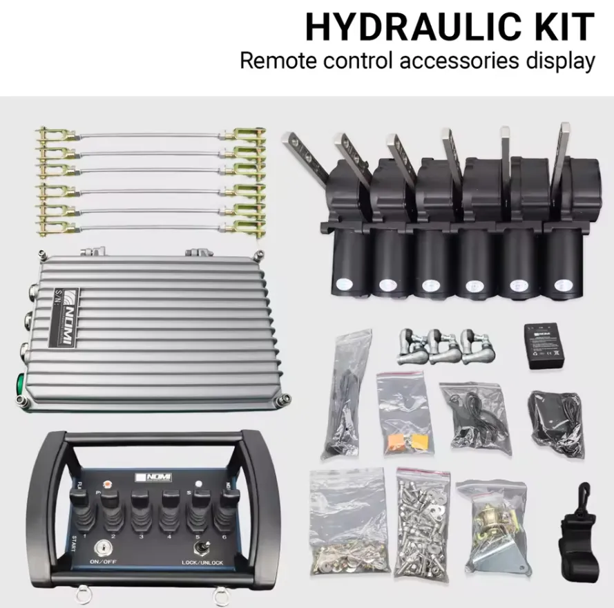
Мы провели испытания и оценку универсальных комплектов беспроводных лебедок на широком спектре транспортных платформ, включая пикапы грузоподъёмностью в полтонны, универсальные грузовики грузоподъёмностью в одну тонну, сельскохозяйственные тракторы, военные платформы LMTV и коммерческие эвакуаторы с платформой. Основное преимущество остается неизменным: устранение физического троса управления из рабочего процесса исключает самую распространённую причину травм, связанных с использованием лебедки, — нахождение оператора в опасной зоне грузового троса во время управления проводным пультом.
Как устроен электрический принцип работы комплекта беспроводного пульта дистанционного управления для универсальной лебедки?
Интерфейс схемы управления соленоидом
Понимание принципа взаимодействия между универсальным комплектом беспроводного пульта дистанционного управления и блоком соленоидов лебедки является отправной точкой для правильной установки и эффективного устранения неисправностей. В каждой электрической лебедке для переключения цепи двигателя с высоким током используется блок соленоидов (также называемый блоком контакторов). Внутри блока соленоидов находятся два соленоида повышенной прочности: один для движения двигателя вперед (втягивание лебедки) и один для движения двигателя назад (вытягивание лебедки). Катушки соленоидов работают при низком токе (обычно 1–3 ампера при напряжении 12 В или 24 В) и получают питание от цепи управления — изначально через жестко подключенный подвесной пульт.
The wireless receiver kit simply intercepts this control circuit signal. The receiver’s two relay outputs connect in parallel with the existing pendant plug connections at the solenoid pack. When the receiver activates Relay 1, it applies the control voltage to the “winch in” solenoid coil. When it activates Relay 2, it applies control voltage to the “winch out” solenoid coil. The solenoids then switch the high-current motor circuit exactly as they would under pendant control.
Последовательность сигналов от нажатия кнопки передатчика до движения двигателя
Полная схема прохождения электрического сигнала в работающем комплекте беспроводной лебедки:
Оператор нажимает кнопку «IN» или «OUT» на передатчике
↓
Микроконтроллер передатчика кодирует команду с указанием уникального идентификатора устройства
↓
РЧ-сигнал, передаваемый на рабочей частоте (433 МГц, 868 МГц или 915 МГц)
↓
Приемная антенна улавливает радиочастотный сигнал
↓
Микроконтроллер приёмника декодирует сигнал и проверяет идентификатор устройства
↓
Соответствующий идентификатор устройства: приемник активирует соответствующий релейный выход
↓
Контакт реле замыкается, подавая управляющее напряжение на катушку соленоида лебедки
↓
Соленоид включается, замыкая контакт цепи двигателя, по которой протекает сильный ток
↓
Двигатель вращается в заданном направлении
↓
Кнопка «Отпустить» на пульте управления: передатчик прекращает передачу сигнала, реле размыкается, соленоид обесточивается, двигатель останавливается
This entire sequence — from button press to motor movement — takes between 50 and 150 milliseconds in a quality system. The motor stopping sequence is equally fast: when the operator releases the button, the transmitter’s hold-to-run (dead man’s) protocol stops the command signal, the receiver drops the relay, the solenoid de-energizes, and the motor stops.
Как питание обеспечивается самим приемником
The receiver unit requires its own low-current power supply (typically 50-200 mA at operating voltage) to power its microcontroller, RF circuitry, and relay coils. In a universal kit, this power comes from the winch’s control circuit — the same switched 12V or 24V supply that powers the solenoid coil circuit. The receiver connects its power input to the vehicle’s accessory power or the winch solenoid pack’s control power supply terminal.
В системах с блоком питания с функцией автоматического определения напряжения приемник оснащен импульсным стабилизатором с широким диапазоном входного напряжения, который принимает любое постоянное напряжение в диапазоне от 10 В до 30 В и обеспечивает стабильное внутреннее рабочее напряжение 5 В или 3,3 В независимо от входного напряжения. Благодаря этому один и тот же физический приемник совместим как с установками на 12 В, так и с установками на 24 В без каких-либо внутренних модификаций.
Требования к номинальным параметрам реле
The relay outputs inside the receiver switch the solenoid coil circuit, not the motor’s main power circuit. The solenoid coil draws typically 1-3 amps at operating voltage. However, the relay must also handle the inductive switching transient when the solenoid coil de-energizes — a voltage spike that can reach 5-10 times the supply voltage in an unprotected circuit. Quality receivers include flyback diodes (also called freewheeling diodes) across each relay output to absorb this inductive transient and protect the relay contacts.
Номинальная нагрузка релейных контактов в приемнике должна составлять не менее 10 А при напряжении 30 В постоянного тока, чтобы с достаточным запасом выдерживать как ток катушки соленоида, так и индуктивные переходные процессы. В приемниках с релейными контактами, рассчитанными лишь на 3–5 А, индуктивное переключение приведет к износу контактов, и они выйдут из строя уже через несколько сотен рабочих циклов.
Какие компоненты входят в комплект универсального беспроводного пульта дистанционного управления лебедкой?
Состав стандартного комплекта
Полный комплект универсального пульта дистанционного управления беспроводной лебедкой, составленный профессионалами, включает в себя следующие элементы. Перед покупкой любого комплекта, в котором отсутствуют элементы из данного списка, следует тщательно его оценить:
| Компонент | Стандартные технические условия | Цель |
|---|---|---|
| РЧ-передатчик (портативный пульт дистанционного управления) | FHSS (фиксированная частота), степень защиты IP65+, кнопки с удерживанием для запуска, специальная кнопка аварийной остановки | Основной интерфейс управления оператора |
| Блок радиочастотного приемника | Протокол сопряжения, IP54+, вход 10–30 В или с заданным напряжением, 2 релейных выхода | Декодирует команды передатчика, активирует соленоиды |
| Крепеж для приемника | Винты из нержавеющей стали, резиновые прокладки, кабельные стяжки | Закрепите приемник на транспортном средстве или лебедке |
| Проводка | С установленными разъемами соответствующего типа, 16–18 AWG, 3–6 футов | Подключите приемник к цепи управления соленоидом |
| Разъемы для соленоидных интерфейсов | Клеммы типа OEM или универсальные плоские/кольцевые клеммы | Подключите к существующему жгуту проводов соленоида |
| Батарейки для передатчика | 2 щелочные батарейки типа AA или комплект перезаряжаемых батареек | Включите портативный передатчик |
| Шнурок для передатчика / ремешок на запястье | Нейлоновая лямка, застежка с механизмом отсоединения | Не снимать передатчик во время работы |
| Антенна (приемник) | Штыревая антенна с разъемом SMA, согласованная для частот 433/868/915 МГц | Прием радиочастотного сигнала |
| Инструкция по установке | Для конкретного языка, со схемой подключения | Рекомендации по установке |
| Инструкция по сопряжению/подключению | Краткое руководство по процедуре переплета | Справочник по перевязке на месте |
Дополнения к комплекту «Премиум»
В универсальных комплектах более высокого качества добавлены компоненты, повышающие надежность, безопасность и упрощающие монтаж:
| Дополнительная опция «Премиум» | Функция | Польза для пользователя |
|---|---|---|
| Погодоустойчивый корпус приемника | Корпус класса защиты IP67 с герметичным кабельным вводом | Защита при эксплуатации на открытом воздухе и в условиях бездорожья |
| Светодиодный индикатор состояния на приемнике | Отображает состояние питания, приема сигнала и срабатывания реле | Возможность диагностики без вскрытия корпуса |
| Звуковой сигнал на приемнике | Звуковые сигналы при срабатывании аварийной остановки или потере сигнала | Уведомляет персонал, находящийся поблизости, об изменении состояния системы |
| Резервный проводной подвесной светильник | Короткий подвесной шнур длиной 3–6 футов в виде спирали с таким же разъемом | Резервное управление на случай сбоя в работе беспроводной системы |
| Светодиодный индикатор заряда аккумулятора автомобиля | Отображает состояние питания схемы управления | Быстрая проверка источника питания |
| Кобура для передатчика на липучке | Крепит передатчик к каркасу безопасности, рулевой колонке или приборной панели | Удобное хранение в перерывах между использованием |
| Аккумуляторный блок для передатчика | Литий-ионный аккумулятор с зарядкой через USB-C | Позволяет избежать затрат на замену батареек типа АА |
Какие марки и модели лебедок совместимы с универсальными комплектами беспроводных пультов дистанционного управления?
Обзор совместимости брендов
Универсальные комплекты беспроводных пультов дистанционного управления предназначены для подключения к стандартному двухпроводному интерфейсу управления соленоидной катушкой, который используется практически во всех электрических грузовых и универсальных лебедках. В приведенной ниже таблице представлены наиболее распространенные марки лебедок и информация об их совместимости:
| Марка лебедки | Распространенные модели | Управляющее напряжение | Тип разъема соленоида | Совместимость с универсальным комплектом |
|---|---|---|---|---|
| Предупреждение | Серия VR, серия XT, Zeon, M8000 | 12 В | 2-контактный разъем Deutsch или с плоскими контактами | Да |
| Smittybilt | X20, XRC, Comp Gen2 | 12 В | Штыревой разъем | Да |
| Superwinch | «Тигровая акула», серия S, серия LT | 12 В | 2-контактный разъем | Да |
| «Rough Country» | Серия Pro, серия Combo | 12 В | Штыревой разъем | Да |
| Westin | HDX, серия Platinum | 12 В | Штыревой разъем | Да |
| Мильный столб | HI/LO, гидравлическая серия | 12 В (электрический) | Штыревой разъем | Да (электрические модели) |
| Comeup | Уплотнение, серия DV | 12 В | 2-контактный разъем | Да |
| Бесплодные земли | Apex, Стандартный | 12 В | Штыревой разъем | Да |
| Runva | Серия EWB, серия EWX | 12 В или 24 В | Штыревой разъем | Да |
| VehicleX | Серия Pro | 12 В | Штыревой разъем | Да |
| Рэмси | Серия REP, Patriot | 12 В или 24 В | 2-контактный разъем | Да |
| Warn (для тяжелых условий эксплуатации) | HS9500i, ZEON Platinum | 12 В | Warn — зарегистрированная торговая марка | Проверить наличие адаптера для конкретной модели |
| Коммерческая лебедка для грузовиков на 24 В | Различные бренды автопарков | 24 В | Лопатка для тяжелых условий эксплуатации или DIN | Да (требуется комплект на 24 В) |
Ситуации, в которых необходимо проверить универсальную совместимость
Хотя двухпроводной интерфейс соленоида является практически универсальным, в случае некоторых конфигураций лебедок необходимо провести дополнительную проверку, прежде чем предполагать, что стандартный комплект подойдет:
Лебедки со встроенным беспроводным модулем, уже установленные: Some newer winch models (particularly from Warn’s upper product lines) include factory wireless systems with proprietary encrypted protocols. Adding a universal kit in parallel will work electrically, but may create confusion if both wireless systems are active simultaneously.
Гидравлические лебедки: Универсальные беспроводные комплекты, предназначенные для электрических лебедок, не обеспечивают прямого управления гидравлическими лебедками, в которых вместо контакторов двигателя типа «вкл./выкл.» используются пропорциональные соленоидные клапаны. Для беспроводного управления гидравлическими лебедками требуются приемники с пропорциональным выходом.
Трехфазные лебедки переменного тока: Для крупных коммерческих лебедок, в которых используются трехфазные двигатели переменного тока и частотно-регулируемые приводы, требуются промышленные беспроводные системы, а не стандартные универсальные комплекты на 12 В/24 В.
Лебедки с соленоидами мгновенного действия и соленоидами постоянного действия: В большинстве лебедок используются соленоиды мгновенного действия (которые должны находиться под постоянным напряжением для поддержания рабочего состояния), что соответствует принципу работы стандартных беспроводных комплектов, требующих удержания кнопки для продолжения работы. В небольшом числе устаревших моделей лебедок используются соленоиды с удержанием или фиксирующие соленоиды — перед выбором комплекта необходимо уточнить тип соленоида.
Как установить универсальный комплект беспроводного пульта дистанционного управления на лебедку с напряжением 12 В или 24 В?
Подготовка к установке
Перед началом установки подготовьте следующую информацию и материалы:
- Confirm the winch’s control circuit voltage (12V or 24V) by checking the winch nameplate or vehicle electrical specification.
- Найдите блок соленоидов на лебедке и определите два разъема управляющих проводов, к которым подключается заводской пульт дистанционного управления.
- Определите место установки приемного блока: по возможности в месте, защищенном от попадания прямых брызг воды, с антенной, ориентированной вертикально для обеспечения всенаправленного покрытия, в пределах досягаемости кабеля от разъема управления соленоидом.
- Убедитесь, что в месте установки приемника имеется источник питания для системы управления (коммутируемое питание 12 В или 24 В, цепь с предохранителем на 3 А как минимум)
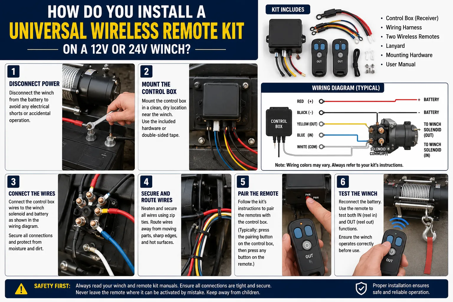
Пошаговая инструкция по установке
Шаг 1: Отключить питание автомобиля
Before making any electrical connections, disconnect the vehicle battery’s negative terminal or engage the main power disconnect switch. This prevents accidental winch activation during installation, which is a documented cause of serious injury.
Шаг 2: Найдите и обеспечьте доступ к разъемам управления соленоидом
On most winches, the factory pendant plugs into a two-wire connector on the solenoid pack’s control harness. This connector typically uses Deutsch DT-series, weatherproof blade, or simple spade terminal connections. Identify:
- The “winch in” control wire (typically labeled IN, +, or colored green on OEM harnesses)
- The “winch out” control wire (typically labeled OUT, -, or colored red or white on OEM harnesses)
- Общий провод или провод обратного хода цепи управления.
Шаг 3: Подключите выводные провода приемника
Connect the receiver’s two relay output wires to the solenoid control circuit using the kit’s provided connectors:
| Провод антенны | Точка подключения | Примечания |
|---|---|---|
| Выход реле 1 (IN) | Вход управления «IN» соленоида лебедки | Проверьте полярность, если соленоид чувствителен к полярности |
| Выход реле 2 (OUT) | Вход управления «ВЫКЛ.» соленоида лебедки | Проверьте полярность, если соленоид чувствителен к полярности |
| Общие точки соприкосновения | Опорная точка заземления шасси транспортного средства или соленоида | Должна иметь общую заземляющую точку с блоком соленоидов |
Шаг 4: Подключение источника питания приемника
Connect the receiver’s power input wires to the vehicle’s control circuit power supply. The positive wire connects to the switched 12V or 24V supply (use the same circuit that powers the solenoid pack, after any inline fuse). The negative wire connects to the vehicle chassis ground near the receiver mounting point.
Шаг 5: Установите приемник
Закрепите приемный блок с помощью прилагаемого крепежа. Важные моменты, которые необходимо учитывать при монтаже:
- Установите антенну снаружи любого металлического корпуса так, чтобы её наконечник был направлен вверх.
- На всех местах прохода кабеля используйте резиновые прокладки, чтобы предотвратить повреждение от истирания.
- Убедитесь, что в месте установки приемник не будет подвергаться воздействию скопившейся воды.
- Keep the receiver at least 150mm away from the winch motor to reduce RF interference from the motor’s brush arcing.
Шаг 6: Соедините передатчик с приемником
Каждый универсальный беспроводной комплект требует прохождения процедуры первоначальной синхронизации для соединения передатчика с приемником. Стандартная процедура:
- Включите питание приемника (подключите к автомобильному аккумулятору).
- Press and hold the receiver’s LEARN or PAIR button for 3-5 seconds until the status LED flashes rapidly.
- На пульте дистанционного управления один раз нажмите любую кнопку движения.
- Индикатор состояния приемника начинает медленно мигать или горит постоянным светом, что подтверждает успешное сопряжение.
- Проверьте работу функций IN и OUT, чтобы убедиться в правильном направлении действия.
Шаг 7: Проверка направления и корректировка
If the transmitter’s IN button causes the winch to pay out rope (wrong direction), swap the receiver’s two relay output connections at the solenoid. This reversal corrects directional mapping without any reprogramming.
Шаг 8: Подключение питания автомобиля и проверка работоспособности всех функций
Подключите обратно отрицательную клемму аккумулятора. Проведите тестирование беспроводного пульта дистанционного управления на всем рабочем диапазоне, проверьте работу функции аварийной остановки (если она предусмотрена в комплекте) и убедитесь, что имеющийся заводской подвесной пульт по-прежнему работает при подключении к сети (для обеспечения возможности двойного управления).
Распространенные ошибки при установке и способы их устранения
| Ошибка | Симптом | Исправление |
|---|---|---|
| Приемник, подключенный к цепи 12 В на лебедке с напряжением 24 В | Приемник включается, но реле издают шумы или работают нестабильно | Заменить на приемник, рассчитанный на напряжение 24 В, или с функцией автоматического определения напряжения |
| Антенна, установленная внутри металлического бампера | Очень малая дальность (менее 5 футов) | Переместить антенну во внешнее положение |
| Обратное подключение выходов реле | Кнопка «IN» разматывает трос, кнопка «OUT» сматывает его | Поменяйте местами два провода, подключенные к выходам реле |
| Заземление подключено к кузовной панели, а не к шасси | Периодическое срабатывание реле, особенно под нагрузкой | Подключите заземление к раме или отрицательному полюсу аккумулятора |
| На релейных выходах отсутствует защита от обратного хода | Резкий отказ контактов реле | Подключите диод 1N4007 поперек каждого входа катушки соленоида, катодом к положительному полюсу |
Какая технология беспроводной связи обеспечивает наибольшую дальность действия и надежность?
Технологические варианты, доступные в универсальных наборах
В универсальных комплектах для дистанционного управления лебедками используются три различных технологии беспроводной связи, каждая из которых имеет свои технические характеристики и компромиссы:
Фиксированная частота 433 МГц (базовая версия):
Самая простая и недорогая технология. Передатчик и приемник работают на одном фиксированном канале в диапазоне ISM 433 МГц. Дальность действия обычно составляет 30–60 футов в идеальных условиях. Помехи от других устройств, работающих на частоте 433 МГц (пульты открывания гаражных ворот, датчики давления в шинах, системы бесключевого доступа), могут приводить к периодическим пропускам команд или ложным срабатываниям. Наилучшим образом подходит для простых задач, когда оператор всегда находится в непосредственной близости от лебедки, а источники радиочастотных помех минимальны.
Фиксированная частота 315 МГц (Северная Америка, старые модели):
Устаревший стандарт, который до сих пор встречается в некоторых наборах, продаваемых на рынках Северной Америки. Характеристики дальности действия и помех аналогичны показателям диапазона 433 МГц. В связи с изменением нормативных требований к распределению радиочастотного спектра этот стандарт постепенно выходит из употребления в пользу диапазона 433 МГц и более высокочастотных вариантов.
Расширенный спектр с переключением частоты (FHSS) на частотах 433 МГц / 868 МГц / 915 МГц:
Рекомендуемая технология для любого серьезного применения в грузовом автотранспорте или в сфере коммунальных услуг. Технология FHSS меняет рабочую частоту сотни раз в секунду, используя псевдослучайную последовательность, синхронизированную между передатчиком и приемником. Это делает систему практически невосприимчивой к помехам от устройств с фиксированной частотой и от других систем FHSS, использующих другие последовательности переключения частот. Дальность действия составляет 100–300 футов в зависимости от конкретной реализации и условий окружающей среды.
Соответствие нормативным требованиям по частотным диапазонам в разбивке по регионам
| Регион | Утвержденные диапазоны частот | Регулирующий орган | Требуемая сертификация |
|---|---|---|---|
| Соединенные Штаты | 315 МГц, 433 МГц, 902–928 МГц | FCC | FCC, часть 15 (требуется идентификатор) |
| Канада | 433 МГц, 902–928 МГц | ISED | RSS-210 |
| Европейский союз | 433,05–434,79 МГц, 868,0–868,6 МГц | ETSI | CE RED 2014/53/ЕС |
| Великобритания | 433 МГц, 868 МГц | Ofcom | UKCA |
| Австралия | 433 МГц, 915–928 МГц | ACMA | RCM |
| Япония | 426 МГц, 429 МГц | MIC | TELEC |
| Китай | 433 МГц, 470–510 МГц | МИИТ | SRRC |
Всегда убеждайтесь, что приобретаемый вами комплект имеет сертификационный знак, требуемый в вашей стране. Использование несертифицированного беспроводного устройства является незаконным практически во всех юрисдикциях и может повлечь за собой штрафы и конфискацию оборудования.
Ожидаемый запас хода в реальных условиях эксплуатации
Manufacturers’ stated range figures are measured under ideal open-field conditions: transmitter and receiver at equal height, no RF interference, no physical obstructions. Real-world range in truck and utility applications is consistently lower:
| Окружающая среда | Типичное снижение запаса хода в реальных условиях | Корректированная дальность (система с номинальной дальностью 100 м) |
|---|---|---|
| Открытое поле, без препятствий | 0% | 100 м |
| Пригородная улица, рядом припаркованные автомобили | 20-30% | 70–80 м |
| Городская среда, плотная застройка | 40-60% | 40–60 м |
| Внутри здания с металлическим каркасом | 50-70% | 30–50 м |
| Густой лес или джунгли | 30-50% | 50–70 м |
| Транспортное средство, находящееся между передатчиком и приемником | 40-60% | 40–60 м |
| Антенна, установленная внутри металлического бампера | 80-90% | 10–20 м |
Для большинства случаев применения лебедок на грузовиках и универсальных транспортных средствах рабочий диапазон в 30–50 футов (10–15 метров) является достаточным с эксплуатационной точки зрения, поскольку оператору необходимо постоянно поддерживать визуальный контакт с тросом и грузом. Дальность действия приобретает большее значение при использовании лебедок на грузовых автомобилях, где оператору может потребоваться управлять лебедкой с противоположной стороны большого транспортного средства или из-за физического препятствия.
Какие элементы безопасности должен включать в себя качественный универсальный комплект пульта дистанционного управления лебедкой?
Обязательные требования к безопасности
Архитектура безопасности комплекта для беспроводного дистанционного управления лебедкой напрямую определяет, обеспечивает ли он защиту операторов в реальных условиях эксплуатации или просто обеспечивает удобство беспроводного управления без каких-либо преимуществ с точки зрения безопасности. Эти функции являются обязательными для любого серьезного применения:
Hold-to-Run (Dead Man’s Control):
Все кнопки управления должны требовать постоянного нажатия для поддержания работы лебедки. Как только оператор отпускает кнопку, лебедка останавливается. Это самая важная мера безопасности, поскольку любое отвлечение внимания, падение пульта или потеря сознания приводят к немедленной остановке лебедки. Комплект с тумблерным (фиксирующим) управлением, при котором лебедка продолжает работать после отпускания кнопки, не следует использовать в тех случаях, когда трос находится вблизи персонала.
Специальная кнопка аварийной остановки:
Отдельная, чётко обозначенная кнопка аварийной остановки, которая мгновенно отключает все релейные выходы и блокирует дальнейшие команды на движение до момента намеренного сброса. Кнопка аварийной остановки должна физически отличаться от кнопок управления движением по размеру, цвету (как правило, красному) и расположению, чтобы её можно было активировать без визуального подтверждения.
Таймаут механизма контроля:
Если приемник теряет сигнал передатчика на время, превышающее заданный тайм-аут (обычно 0,5–2 секунды), он должен автоматически отключить оба релейных выхода и остановить лебедку. Это позволяет избежать ситуации, при которой батарея передатчика разряжается или передатчик выходит за пределы зоны действия во время работы лебедки.
Сопряжение уникального устройства:
Передатчик должен использовать уникальный цифровой код для идентификации перед приемником. В противном случае любой совместимый передатчик, находящийся в зоне действия, сможет управлять лебедкой, что создаст серьезную угрозу непреднамеренного срабатывания на объектах, где эксплуатируется несколько транспортных средств.
Предупреждение о низком заряде батареи:
Передатчик должен подавать звуковой и/или визуальный сигнал предупреждения, когда напряжение батареи опускается ниже порогового значения, при котором можно гарантировать надежную радиочастотную передачу, причем предупреждение должно поступать с достаточным запасом времени, чтобы завершить текущую операцию и заменить батареи до отключения устройства.
Сравнение функций безопасности в комплектах разных уровней качества
| Функция безопасности | Бюджетный набор | Комплект среднего уровня | Профессиональный набор |
|---|---|---|---|
| Управление режимом «удерживай для движения» | Да | Да | Да |
| Специальная кнопка аварийной остановки | Нет | Да | Да (грибовидная голова) |
| Таймаут механизма контроля | 2–5 секунд | 1–2 секунды | 0,5–1 секунда (регулируемое значение) |
| Уникальный код сопряжения | 8-битный (256 кодов) | 16-разрядный (65 536 кодов) | 32-разрядный (более 4 миллиардов кодов) |
| Предупреждение о низком заряде батареи | Только светодиод | Светодиод + звуковой сигнализатор | Светодиод + звуковой сигнал + блокировка передатчика |
| Направленная блокировка | Нет | Иногда | Да (предотвращает одновременные операции IN+OUT) |
| Светодиодный индикатор состояния приемника | Одноцветный | Многоцветный | Многоцветный + ЖК-дисплей |
| Степень защиты (передатчик) | IP54 | IP65 | IP67 |
| Степень защиты (приемник) | IP54 | IP65 | IP67 |
| Сертификация FCC/CE | Самопровозглашённый | Сертифицированный | Подтверждено документально |
Направленная блокировка: почему это важно
Качественный приемник оснащен электронной блокировкой, которая физически предотвращает одновременную активацию обоих релейных выходов. Если реле IN и OUT замыкаются одновременно, оба соленоида лебедки получают питание одновременно, что приводит к короткому замыканию в блоке соленоидов, которое может привести к перегоранию катушек соленоидов и повреждению цепей контакторов двигателя. Эта блокировка должна быть реализована на аппаратном уровне (в схеме подключения контактов реле), а не только программно, чтобы гарантировать её работу даже в случае сбоя прошивки микроконтроллера приемника.
Чем отличаются лебедочные системы на 12 В и 24 В и как это влияет на выбор комплекта дистанционного управления?
Различия в архитектуре электрических систем
The voltage difference between 12V and 24V winch systems reflects the host vehicle’s electrical architecture and has cascading effects on current levels, cable sizing, component specifications, and remote kit selection:
| Технические характеристики | Система 12 В | Система 24 В |
|---|---|---|
| Типичный тип транспортного средства | Легковые автомобили, внедорожники, легкие коммерческие автомобили | Грузовые автомобили, тяжелая техника, военная техника, сельскохозяйственная техника |
| Напряжение двигателя лебедки | 12 В постоянного тока | 24 В постоянного тока |
| Пиковый ток двигателя (лебедка грузоподъемностью 9 500 фунтов) | 380–450 А | 190–225 А |
| Ток в катушке соленоида | 1-2A | 0,5–1 А |
| Сечение силового кабеля (главная цепь) | 2/0–4/0 AWG | 1/0–2/0 AWG |
| Чувствительность к падению напряжения | Высокий (больший перепад напряжения на единицу сопротивления) | Низкий (меньший перепад напряжения на единицу сопротивления) |
| Аккумуляторная система | Один аккумулятор на 12 В или два аккумулятора на 12 В, соединенные параллельно | Две батареи на 12 В, соединенные последовательно (номинальное напряжение 24 В) |
| Выходная мощность генератора | 12 В, 130–270 А | 24 В, 70–150 А |
Почему системы на 24 В обладают практическими преимуществами
При одинаковой выходной мощности система на 24 В потребляет в два раза меньше тока, чем система на 12 В. Такое снижение потребляемого тока вдвое означает:
- Можно использовать силовые кабели меньшего диаметра, сохраняя при этом тот же падение напряжения.
- Контакты соленоида и реле нагреваются меньше, поскольку при той же мощности нагрев по формуле I²R снижается благодаря 75%.
- Падение напряжения на соединителях и участках кабеля приводит к меньшему снижению производительности.
- Двигатель лебедки получает более стабильное напряжение во время интенсивного тягового усилия, что позволяет поддерживать крутящий момент даже при падении напряжения аккумулятора под нагрузкой.
For fleet operators managing large numbers of utility trucks, the 24V system’s reduced cable complexity and improved voltage regulation under load are meaningful operational advantages.
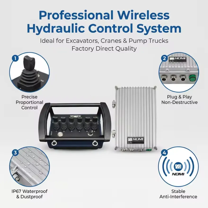
Приемники с функцией автоматического определения параметров: универсальное решение для смешанных автопарков
Менеджеры по закупкам автопарков, отвечающие за парки, состоящие из автомобилей с разными напряжениями питания (12 В и 24 В), сталкиваются с проблемой при выборе комплектов беспроводных лебедок: необходимость поддерживать два отдельных артикула для одного и того же функционального продукта. Приемники с функцией автоматического определения напряжения решают эту проблему за счет встроенного импульсного источника питания с широким диапазоном входного напряжения, который автоматически определяет и регулирует любое входное постоянное напряжение в диапазоне от 10 В до 30 В. Одна модель приемника поддерживает оба системных напряжения без каких-либо модификаций или перенастроек.
The auto-sensing feature also provides protection against transient voltage spikes common in commercial vehicle electrical systems. During engine cranking, the vehicle’s electrical system voltage drops briefly below 10V; during load dump events (sudden disconnection of a large inductive load), voltage can spike above 30V. A wide-input regulated receiver handles both extremes without damage.
Чем универсальные беспроводные комплекты отличаются от оригинальных систем дистанционного управления лебедкой?
Сравнение «один на один»
| Коэффициент сравнения | Универсальный беспроводной комплект | Беспроводной пульт дистанционного управления OEM/заводского производства |
|---|---|---|
| Стоимость приобретения | $30-$150 | $80–$350 (часто продаются по отдельности) |
| Совместимость с лебедкой | Различные бренды и модели | Для одной конкретной марки/модели |
| Наличие запасных частей | Широко доступны, множество поставщиков | Только для OEM-производителей, может быть снят с производства |
| Сложность установки | Средняя сложность (требуется подключение) | Низкий (разъем) |
| Протокол сигнала | Стандартизированный или FHSS | Собственное шифрование (более безопасно) |
| Глубина функции | Базовые входы/выходы + аварийная остановка | Иногда включает в себя регулировку скорости и диагностику |
| Диапазон | 30–300 футов (в зависимости от модели) | 50–150 футов (большинство оригинальных пультов дистанционного управления) |
| Долговечность | IP54–IP67 (в зависимости от модели) | IP54–IP65 (большинство устройств OEM) |
| Гибкость при формировании пар | Возможность сопряжения нескольких передатчиков | Часто ограничивается устройствами, сопряжёнными на заводе |
| Устойчивость к помехам | Модели FHSS: превосходные | Зависит от реализации конкретного производителя оборудования |
| Последствия с юридической точки зрения и в отношении гарантии | Может повлиять на действие гарантии на лебедку | Не влияет на гарантию |
Когда универсальные комплекты превосходят системы оригинального производителя
Универсальные комплекты обеспечивают более выгодные условия в трёх конкретных случаях:
Модернизация устаревших лебедок: When an existing winch’s factory remote system is discontinued, damaged, or simply not available in the replacement market, a universal kit provides full wireless functionality at a fraction of the cost of replacing the entire winch. We have seen numerous cases where a quality universal kit extended a perfectly functional winch’s service life by 5-10 years.
Стандартизация мультибрендового автопарка: Оператор автопарка, эксплуатирующий 40 автомобилей, оснащённых лебедками трёх разных марок, может перейти на единую универсальную модель беспроводного комплекта, что упростит управление запасами запасных частей, обучение операторов и процедуры технического обслуживания. Попытки поддерживать запасы оригинальных дистанционных пультов от трёх разных производителей значительно усложняют процесс закупок.
Требования к увеличенной дальности: Некоторые универсальные комплекты FHSS, представленные на рынке, обеспечивают большую эффективную дальность действия, чем заводские пульты, которые они заменяют, поскольку в них используется более совершенная радиочастотная технология, чем во многих заводских беспроводных системах.
Какие основные технические характеристики следует проверить перед покупкой универсального комплекта пульта дистанционного управления лебедкой?
The Buyer’s Specification Checklist
| Технические характеристики | Что нужно проверить | Минимальное допустимое значение |
|---|---|---|
| Диапазон входного напряжения | С автоматическим определением или с фиксированным напряжением | Должно соответствовать системе вашего автомобиля (12 В или 24 В) |
| Номинальный ток релейного выхода | Номинальная токовая нагрузка контактов реле | Не менее 10 А при напряжении системы |
| Беспроводные технологии | Фиксированная частота или FHSS | FHSS — явное предпочтение |
| Рабочий диапазон | Manufacturer’s stated range | Не менее 30 м для стандартного использования |
| Степень защиты передатчика по стандарту IP | Степень защиты корпуса по стандарту IP | Степень защиты не ниже IP65 для использования на открытом воздухе и в условиях бездорожья |
| Класс защиты IP приемника | Степень защиты корпуса по стандарту IP | Минимальный класс защиты IP65 для монтажа на открытом воздухе |
| Рабочая температура | Диапазон минимальной и максимальной температур | от -20 °C до +70 °C (минимум) |
| Управление режимом «удерживай для движения» | Поведение кнопок | Должно быть с режимом «удерживай для работы»; кнопки без фиксации положения |
| Функция аварийной остановки | Специальная кнопка аварийной остановки | Обязательно для любой заявки, связанной с риском по линии нагрузки |
| Таймаут механизма контроля | Время реакции на потерю сигнала | Менее 2 секунд |
| Сертификация в соответствии с нормативными требованиями | Маркировки FCC, CE, RoHS | Matching your country’s requirement |
| Соотношение длины кода | Количество битов уникального идентификатора | Минимум 16-разрядная версия для однокомпьютерных сайтов; 32-разрядная версия для многокомпьютерных сайтов |
| Срок службы аккумулятора | Количество часов работы на один комплект | Более 40 часов для щелочных батареек AA |
| Гарантийный срок | Гарантия производителя | Не менее 12 месяцев |
| Наличие запасных передатчиков | Можно ли приобрести дополнительные передатчики? | Должно быть доступно отдельно |
Матрица соотношения «цена-качество»
| Ценовой диапазон (долл. США) | Типичный уровень качества | Основные ограничения | Лучшее приложение |
|---|---|---|---|
| $25-$60 | Бюджет | Фиксированная частота, IP54, малый радиус действия, без аварийной остановки | Нечастое использование, контролируемые условия эксплуатации |
| $60-$120 | Средний ценовой диапазон | FHSS или усовершенствованная стационарная система, IP65, аварийная остановка, дальность действия 50–100 м | Стандартный внедорожник, грузовик общего назначения, повседневное использование |
| $120-$200 | Профессиональный | FHSS, IP67, настраиваемый сторожевой таймер, полный набор функций безопасности, дальность действия 100–300 м | Коммерческий автопарк, повседневное использование, опасные условия эксплуатации |
| $200+ | Промышленный | FHSS-шифрование, степень защиты IP68, класс безопасности PLc, полная документация | Критически важная инфраструктура, крупный коммерческий сектор |
Какие процедуры технического обслуживания и устранения неисправностей позволяют обеспечить надежную работу вашего комплекта беспроводной лебедки?
График профилактического технического обслуживания
| Интервал | Задача | Инструменты/материалы |
|---|---|---|
| Перед каждым использованием | Проверить работу кнопок IN и OUT; проверить индикатор заряда батареи передатчика; осмотреть корпус передатчика на наличие трещин | Визуальный осмотр |
| Ежемесячно | Протрите антенну приемника сухой тканью; проверьте кабельные соединения на наличие потертостей; убедитесь, что крепежные элементы приемника затянуты | Динамометрический ключ, салфетка для чистки |
| Ежеквартально | Проверьте соединения выходных контактов реле на соленоиде на наличие коррозии; проверьте работу во всем диапазоне; осмотрите состояние уплотнений на передатчике и приемнике | Диэлектрическая смазка, средство для очистки контактов |
| Ежегодно | Замените батареи датчика независимо от состояния индикатора; проверьте контакты реле с помощью мультиметра; проверьте работу функции аварийной остановки и время ожидания сторожевого таймера | Мультиметр, запасные батарейки |
| После погружения | Проверить уплотнения корпуса приемника; просушить передатчик; провести проверку работоспособности перед возвращением в эксплуатацию | Чистая сухая ткань, визуальный осмотр |
Систематическое устранение неисправностей: пошаговая диагностика неисправностей
| Симптом | Наиболее вероятная причина | Этап диагностики | Резолюция |
|---|---|---|---|
| Ни одна кнопка не реагирует | Разряженная батарея передатчика | Измерьте напряжение батареи (для 4 батареек типа AA оно должно быть выше 4,5 В) | Заменить батарейки |
| Ответа нет, новые батарейки | Связь между передатчиком и приемником прервана | Проверьте состояние светодиода приемника; попробуйте выполнить процедуру повторной привязки | Перепрограммировать передатчик в соответствии с инструкциями производителя |
| Очень малая дальность (менее 3 метров) | Антенна, установленная внутри металлического корпуса | Визуально проверьте расположение антенны | Переместить антенну во внешнее положение |
| Прерывистый отклик | Разряженный аккумулятор или радиочастотные помехи | Проведите тестирование с близкого расстояния; замените батарейки; проверьте наличие источников помех | Замените батареи; переключитесь на менее загруженную частоту, если используется комплект с фиксированной частотой |
| Лебедка вращается в неправильном направлении | Провода релейного выхода перепутаны | Сверьте проводку со схемой монтажа | Поменяйте местами два провода, подключенные к выходам реле |
| Оба направления работают одновременно | Сбой блокировки направления | Проверьте проводку выхода реле на наличие короткого замыкания | Убедитесь в правильности подключения; при внутренней неисправности блокировки замените приемник |
| Лебедка работает без нажатия кнопки | Реле срабатывания при радиочастотных помехах | Проверить наличие устройств, работающих на частоте 433 МГц, вблизи | Перейдите на комплект FHSS или переместите приемник подальше от источника помех |
| Приемник произвольно выключается | Падение напряжения питания при нагрузке на лебедку | Измерьте напряжение питания приемника во время работы лебедки | Установите конденсатор в цепь питания приемника; улучшите прокладку кабеля питания |
| Аварийная остановка не останавливает лебедку | Аварийный выключатель не подключен к цепи безопасности | Проверить подключение цепи аварийной остановки | Выполните переподключение в соответствии с инструкцией к набору; добавьте встроенную кнопку аварийной остановки, если в наборе её нет |
В каких отраслях и для каких типов транспортных средств используются универсальные комплекты беспроводных пультов дистанционного управления лебедками?
Внедрение приложений по отраслям
| Отрасль / Область применения | Тип транспортного средства | Напряжение системы лебедки | Основные требования к комплекту дистанционного управления |
|---|---|---|---|
| Внедорожный отдых | Пикап, внедорожник | 12 В | IP67, FHSS, компактный передатчик |
| Сельское хозяйство / ферма | Трактор, квадроцикл, UTV | 12 В или 24 В | Автоматическое определение напряжения, прочный корпус |
| Коммунальные услуги и телекоммуникации | Грузовой автомобиль, фургон | 12 В или 24 В | Кнопки с большим радиусом действия, удобные для использования в перчатках |
| Лесное хозяйство и древесина | Трелевочная машина, сельскохозяйственный трактор | 24 В | IP67, приспособленность к эксплуатации в холодных климатических условиях, большой радиус действия |
| Строительство | Плоскоплатформенный грузовик, автокран | 12 В или 24 В | FHSS, аварийная остановка, профессиональный уровень |
| Военная сфера и оборона | LMTV, HMMWV, JLTV | 24 В | Автоматическое распознавание, зашифрованное сопряжение, прочная конструкция |
| Поисково-спасательные работы | Спасательный грузовик с полным приводом | 12 В | IP67, удобный для использования в перчатках, надежный аварийный выключатель |
| Морской / прибрежный | Рабочий катер, погрузчик для причала | 12 В | IP68, фурнитура из нержавеющей стали, устойчивость к коррозии |
| Буксировка и эвакуация | Тяжелый эвакуатор, эвакуатор с подъемной платформой | 12 В или 24 В | Поддержка большого радиуса действия и нескольких передатчиков |
| Горнодобывающая площадь | Сервисный грузовик, легковой автомобиль | 24 В | FHSS, IP67, искробезопасные контакты |
| Коммунальные услуги | Сервисный грузовик, снегоуборочная машина | 12 В или 24 В | Автоматическое определение параметров, работоспособность в холодную погоду |
Почему универсальные беспроводные комплекты наиболее выгодны для коммунальных грузовиков
Служебные грузовики, эксплуатируемые бригадами телекоммуникационных компаний, электроэнергетических предприятий и коммунальных служб, представляют собой наиболее убедительный практический пример необходимости использования универсальных комплектов для дистанционного управления лебедками по беспроводной связи. На этих транспортных средствах лебедки используются непрерывно в течение всей смены — для буксировки кабельных барабанов, установки оборудования, вытаскивания застрявших транспортных средств — и операторам часто приходится менять положение относительно транспортного средства для управления рабочим процессом.
Проводной пульт управления ограничивает зону нахождения оператора расстоянием 10–15 футов от лебедки и вынуждает его во время работы располагаться непосредственно рядом с грузовым тросом. Беспроводной комплект с радиусом действия 50–100 футов позволяет оператору находиться на рабочей площадке — в точке окончания кабеля, рядом с устанавливаемым оборудованием или в безопасном месте наблюдения — при этом сохраняя полный контроль над лебедкой. Мы постоянно фиксируем повышение производительности на 20–35% при работе бригад коммунальных служб после перехода с пульта с проводом на беспроводное управление лебедкой, в первую очередь потому, что оператору реже приходится возвращаться к лебедке для регулировки положения пульта.
Часто задаваемые вопросы (FAQ)
1: Будет ли универсальный комплект беспроводного пульта дистанционного управления работать с лебедкой именно моей марки?
A universal wireless remote kit is compatible with any electric winch that uses a standard two-solenoid control circuit, which includes virtually all consumer and professional electric truck winches from brands including Warn, Smittybilt, Superwinch, Rough Country, Comeup, Runva, Badlands, and hundreds of smaller manufacturers. Compatibility is confirmed by checking two things: the control circuit voltage (must match the kit’s input rating or fall within the auto-sensing range), and the solenoid connector type (most kits include multiple connector adapters or bare wire ends that connect to any terminal type). The only winch types that a standard universal kit does not directly support are hydraulic winches (which use proportional solenoid valves), three-phase AC winches, and winches with proprietary encrypted factory wireless systems that actively block parallel control inputs.
2: Как определить, установлена ли на моем грузовике лебедочная система на 12 В или 24 В?
Confirming your winch system voltage takes less than two minutes. The most reliable method is to check the winch’s nameplate, which is typically affixed to the motor housing or gear case and lists the operating voltage as “12V DC” or “24V DC.” Alternatively, measure the voltage at the winch power cable terminals with the engine running using a multimeter: a 12V system reads approximately 13.5-14.5V at the battery with the engine running; a 24V system reads approximately 27-29V. Vehicle-level verification: check the battery configuration under the hood. A single battery or two batteries wired in parallel (both positive terminals connected together, both negative terminals connected together) is a 12V system. Two batteries with positive from one connected to negative of the other (series connection) is a 24V system. Commercial trucks, military vehicles, and most agricultural tractors use 24V systems.
3: Какова оптимальная дальность действия универсального пульта дистанционного управления для беспроводной лебедки?
В большинстве случаев использования лебедок на грузовиках эффективная рабочая дальность от 30 до 50 футов (от 10 до 15 метров) покрывает подавляющее большинство практических ситуаций. Оператор должен всегда поддерживать визуальный контакт с тросом и грузом, который поднимается или перемещается, что, как правило, и так удерживает его в пределах 30–50 футов от лебедки. Однако выбор комплекта с номинальной дальностью 100 футов (30 метров) или более обеспечивает значительный запас безопасности в двух случаях: на больших грузовиках коммунального назначения, где оператору приходится работать на дальнем конце длинной платформы, в то время как лебедка находится в передней части, а также в ситуациях, когда оператору необходимо расположиться за физическим барьером (кузовом транспортного средства, бетонным барьером) для защиты, сохраняя при этом контроль над лебедкой. Для таких задач комплект FHSS с номинальной дальностью 100 метров обеспечивает надёжную работу на расстоянии 50 футов с запасом.
4: Можно ли установить комплект беспроводного пульта дистанционного управления на лебедку, которая уже оснащена заводским беспроводным пультом?
Yes, adding a universal wireless kit in parallel with an existing factory wireless system is electrically straightforward: both systems connect to the same solenoid control inputs, and whichever system’s relay is active at any given moment controls the winch. In practice, both systems work independently, and the factory system continues to function exactly as before. The only operational concern is ensuring only one system is used at a time to avoid sending conflicting commands simultaneously. If the factory system uses a latching (toggle) control rather than hold-to-run, disable or remove the factory system before adding a hold-to-run universal kit, as the operational difference between the two could confuse operators who alternate between them.
5: Как долго работают батарейки передатчика в универсальном беспроводном пульте дистанционного управления лебедкой?
Transmitter battery life in a universal wireless winch remote depends on the transmitter’s RF power output, the duty cycle (how frequently buttons are pressed), and the battery type. Under typical truck recovery or utility use with moderate duty cycle, a set of 4 × AA alkaline batteries lasts approximately 40 to 80 hours of active use. Light-duty recreational use may extend this to 3-6 months of calendar time. Heavy commercial use with frequent activations may consume a set in 2-4 weeks. The transmitter’s sleep mode function — which powers down the RF circuitry when no buttons have been pressed for a pre-set time, typically 30 seconds to 5 minutes — has the largest single impact on battery life. A transmitter with an aggressive sleep mode can extend battery life by 50-70% compared to one that stays continuously active. Kits with rechargeable lithium-ion packs typically provide 20-40 hours per charge and eliminate alkaline battery replacement costs for high-cycle users.
6: Безопасно ли оставлять пульт дистанционного управления беспроводной лебедкой постоянно установленным и подключенным к источнику питания?
Leaving the receiver powered continuously is electrically safe for the receiver itself, as its quiescent current draw is minimal (typically 20-50mA). However, continuous power creates a permanent vulnerability: any valid transmitter command that reaches the receiver will activate the winch, even when the vehicle is parked and unattended. To mitigate this risk, most installations connect the receiver to a switched power source (the vehicle’s ignition-switched accessory circuit or a manually operated switch) so that the receiver only receives power when the vehicle is in active use. Some professional installations add a physical lockout switch on the receiver mounting bracket, allowing the receiver to be powered down independently of the vehicle ignition. Never leave a continuously powered receiver with the winch under loaded tension (rope taut against an anchor), as an inadvertent signal could suddenly release tension or increase it beyond safe limits.
7: Что означает сертификация FCC для пульта дистанционного управления беспроводной лебедкой и является ли она обязательной?
FCC (Federal Communications Commission) certification is the U.S. government authorization required before any intentional RF-transmitting device can be legally sold or operated in the United States. Under FCC Part 15, any wireless remote control device must be tested by an FCC-recognized laboratory and receive a unique FCC ID number that is displayed on the product label. Using a wireless winch remote without FCC certification in the United States is technically a violation of FCC regulations, regardless of whether the device is purchased online from an international supplier. Beyond the legal requirement, FCC certification provides practical assurance: it confirms the device has been tested to operate within its authorized frequency band without excessive transmit power that could interfere with other services. For EU markets, CE marking under the Radio Equipment Directive (RED) 2014/53/EU serves the equivalent function. Always verify the certification marking matches your country’s requirement.
8: Может ли один универсальный комплект беспроводного пульта дистанционного управления управлять несколькими лебедками на одном и том же транспортном средстве?
Для управления несколькими независимыми лебедками с помощью одного беспроводного пульта дистанционного управления требуется либо комплект с несколькими каналами релейного выхода (по одному на каждую лебедку), либо несколько комплектов с разными кодами сопряжения. Стандартные универсальные комплекты имеют два релейных выхода (IN и OUT для одной лебедки). Если на вашем автомобиле установлены две лебедки — типичная конфигурация для тяжёлых эвакуаторов, оснащённых как передней, так и задней лебедками, — у вас есть два варианта. Во-первых, можно приобрести универсальный комплект для двух лебедок, который имеет четыре релейных выхода (передний IN, передний OUT, задний IN, задний OUT) и функциональные кнопки для выбора активной лебедки. Во-вторых, можно приобрести два отдельных комплекта с разными кодами сопряжения, используя один пульт для передней лебедки, а второй — для задней. Вариант с комплектом для двух лебедок предпочтительнее с точки зрения эксплуатации, поскольку оператору достаточно иметь при себе только один пульт, что снижает риск включения не той лебедки из-за того, что он взял не тот пульт.
9: Как подключить запасной передатчик к приёмнику, если оригинальный утерян?
Pairing a replacement transmitter to an existing receiver follows the same binding procedure used during initial installation. Power on the receiver, then press and hold the LEARN or PAIR button on the receiver housing for 3-5 seconds until the status LED enters pairing mode (typically rapid flashing). On the new transmitter, press any motion button once. The receiver stores the new transmitter’s unique code and confirms with a LED status change. Most receivers can store 1-4 transmitter codes simultaneously, so if the receiver already has the maximum number stored, you may need to clear the receiver’s memory (usually by holding the LEARN button for 10+ seconds) and re-pair all transmitters from scratch. This is why we consistently recommend purchasing a spare transmitter at initial installation and performing a simultaneous pairing of both units, which eliminates the memory-clearing step if the primary is ever lost.
10: В чём заключается разница между релейным и полупроводниковым приёмником в комплекте для дистанционного управления лебедкой?
Relay-based receivers use electromagnetic relays — electromechanical switches with physical contacts — to switch the solenoid coil circuit. Solid-state receivers use semiconductor switching devices (MOSFETs or triacs) instead of mechanical contacts. For winch remote applications, relay-based receivers are the dominant design and the preferred choice for several practical reasons. Relay contacts are inherently galvanically isolated from the receiver’s electronics, meaning a solenoid voltage transient cannot damage the receiver’s control circuitry. Relays tolerate the inductive switching transients from solenoid coil de-energization better than unprotected solid-state devices. Relay failures are easy to diagnose (click sound on activation is absent; resistance across contacts is measurable with a multimeter) and relays are inexpensive to replace. Solid-state receivers can switch faster and generate no audible click, but they require more careful transient protection design and are more difficult to field-diagnose. For standard truck and utility winch remote applications, a well-designed relay receiver with 10A minimum contact rating is the most reliable and maintainable solution.
Подтверждаемые источники и ссылки
Технические характеристики, электротехнические стандарты, нормативные требования и рекомендации по безопасности, приведенные в данной статье, основаны на следующих авторитетных первоисточниках:
- FCC, часть 15 — Радиочастотные устройства, подразделы B и C (Федеральная комиссия по связи США) — Требования регулирующих органов США к бескомиссионным беспроводным устройствам, включая пульты дистанционного управления лебедками.
- Директива ЕС о радиооборудовании 2014/53/ЕС (RED) (Европейский парламент и Совет) — Нормативно-правовая база ЕС в отношении устройств беспроводной передачи данных, подлежащих маркировке CE.
- ETSI EN 300 220-2 V3.2.1 — Устройства ближнего действия, работающие в диапазоне частот от 25 МГц до 1 000 МГц (Европейский институт стандартов в области телекоммуникаций) — Технический стандарт для беспроводных устройств, работающих в диапазоне ISM, на рынках ЕС.
- ISO 23853:2021 — Краны. Системы радиоуправления (Международная организация по стандартизации) — Международный стандарт для систем радиоуправления подъемным и тяговым оборудованием, применимый к принципам проектирования беспроводных систем дистанционного управления лебедками.
- SAE J706 — Лебедки (SAE International) – Методика испытаний и классификации автомобильных лебедок.
- EN 14492-1:2006+A1:2009 — Краны: лебедки с механическим приводом (Европейский комитет по стандартизации) — Европейский технический стандарт, устанавливающий требования к конструкции и эксплуатационным характеристикам лебедок.
- IEC 60529 — Степени защиты, обеспечиваемые корпусами (код IP) (Международная электротехническая комиссия) — система классификации степени защиты (IP) для электронных корпусов.
- OSHA 29 CFR 1910.179 — Мостовые и козловые краны (Управление по охране труда и промышленной безопасности США) — Требования безопасности к моторизованному подъемно-тяговому оборудованию.
- ISO 13849-1:2023 — Безопасность машин: элементы систем управления, связанные с безопасностью (Международная организация по стандартизации) — Система оценки уровней надежности, применимая к функциям обеспечения безопасности лебедок.
- NFPA 70: Национальный электротехнический кодекс (NEC), издание 2023 года (Национальная ассоциация пожарной безопасности) — Требования к электропроводке в автомобильных электрических системах.
- IEC 60068-2-32 — Испытания на воздействие окружающей среды: свободное падение (Международная электротехническая комиссия) — Стандарт испытаний на падение для оценки долговечности электронного оборудования.
- ACMA (Австралийское управление по коммуникациям и средствам массовой информации) — Стандарты в области радиосвязи (устройства ближнего действия) – Австралийские нормы распределения частот и технические требования к беспроводным устройствам ближнего действия.
- Техническая документация компании Warn Industries — Соленоиды лебедок и системы управления – Техническое руководство по архитектуре блока соленоидов и техническим характеристикам схем управления лебедок Warn.
Переведите свою лебедку на беспроводное управление с помощью Nomi
Компания Nomi поставляет универсальные комплекты беспроводных пультов дистанционного управления, разработанные специально для лебедок грузовых автомобилей и технических транспортных средств с напряжением 12 В и 24 В. Эти комплекты оснащены технологией FHSS, обеспечивающей работу без помех, передатчиками с классом защиты IP67, гарантирующими надежность в любых погодных условиях, а также приемниками с функцией автоматического определения напряжения, которые поддерживают обе системы напряжения в рамках одного устройства.
Каждый универсальный беспроводной комплект Nomi поставляется с полным пакетом сертификационной документации FCC и CE, предварительно сопряженным запасным передатчиком, полным комплектом проводов с адаптерами с несколькими разъемами для наиболее распространенных конфигураций соленоидов, а также с двухлетней гарантией на замену всех компонентов.
Свяжитесь с нашим отделом продаж уже сегодня для получения информации о оптовых ценах при заказе для автопарка, подтверждения индивидуальных технических характеристик напряжения или проверки технической совместимости конкретной модели лебедки. Мы осуществляем доставку по всему миру, а стандартные товары, имеющиеся в наличии, отправляем в день заказа.
Закажите бесплатную проверку совместимости или скачайте руководство по установке универсального пульта дистанционного управления лебедкой Nomi, чтобы убедиться в правильности своего выбора перед оформлением заказа.