

Heavy duty industrial wireless remote controls rated IP67 with 6 to 12 key configurations are the gold standard for safe, reliable crane, hoist, and winch operation across manufacturing, steel processing, mining, port handling, and hazardous environment applications in 2026. An IP67-rated industrial remote system provides complete dust exclusion and withstands temporary water immersion to one meter depth, ensuring uninterrupted operation in the harshest plant environments. Combined with frequency-hopping spread spectrum radio technology and safety architectures meeting ISO 23853 and Performance Level PLd requirements, these systems deliver the operational reliability and regulatory compliance that procurement engineers and safety managers demand.
If your project requires the use of Industrial Wireless Remote Control, you can contact us for a free quote.
What Makes a Heavy Duty IP67 Industrial Wireless Remote Different from Standard Crane Remotes?
Heavy duty industrial wireless remote controls rated IP67 occupy a distinct product category that sits well above the consumer and light commercial wireless pendant market. The differences are not cosmetic — they reflect fundamentally different engineering standards, materials, manufacturing tolerances, and safety certification requirements that determine whether a remote control system survives five years of daily production use or fails within one season.
The IP67 rating itself is the starting point for the distinction. Under IEC 60529, an IP67 classification means the enclosure prevents all dust ingress (the first digit “6” represents complete dust exclusion) and withstands immersion in water to one meter depth for 30 minutes (the second digit “7”). Achieving and maintaining this rating across the transmitter’s keypad, button seals, housing joints, lanyard attachment points, and antenna penetrations requires precision injection-molded housings with multi-layer gasket systems, chemically bonded overmold rubber sections, and rigorously tested seal integrity at every potential ingress point.
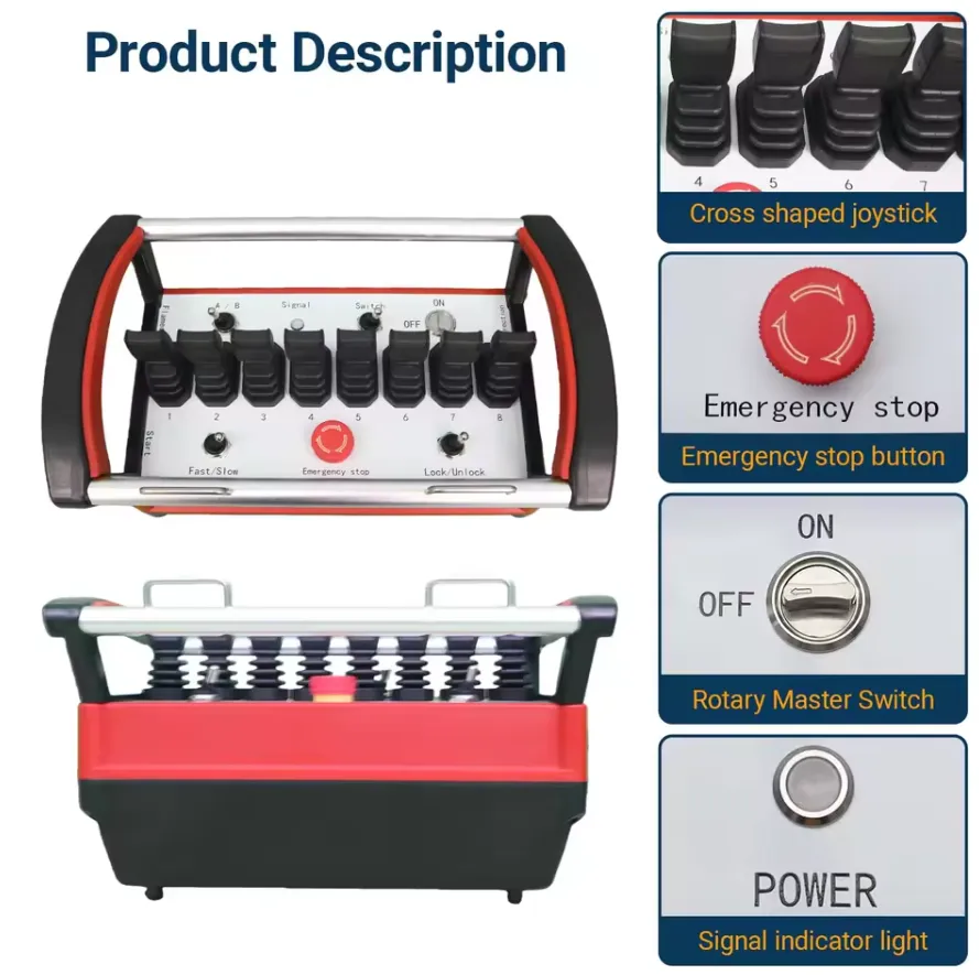
Beyond the IP rating, heavy duty industrial remotes differ from standard products in five additional dimensions:
Operating Temperature Range: Standard consumer remotes are typically rated from -10°C to +55°C. Heavy duty industrial units extend this to -40°C to +85°C, accommodating steel mill environments where radiant heat from furnaces raises ambient temperatures well above 60°C, and cold storage or northern outdoor applications where winter temperatures drop far below the consumer rating floor.
Vibration and Shock Resistance: Industrial cranes, particularly in steel processing, mining, and port handling, generate continuous structural vibration through hook impacts, load swings, and bridge travel over imperfect rail joints. Heavy duty remotes are tested to IEC 60068-2-6 (sinusoidal vibration) and IEC 60068-2-27 (mechanical shock) at levels that reflect real operational exposure, not laboratory minimums.
Drop Resistance: A production environment remote control transmitter gets dropped. Repeatedly. Heavy duty industrial units are designed to survive a 1.5 to 2.0 meter drop onto concrete without functional failure, achieved through glass-fiber reinforced polycarbonate shells, energy-absorbing rubber overmolds, and internal component mounting systems that isolate circuit boards from impact forces.
Electrical Safety Category: Heavy duty systems target Performance Level PLd (Category 3 per ISO 13849-1) as a minimum, with dual-channel safety relay architectures in the receiver, monitored E-stop circuits, and documented risk assessments. Standard commercial remotes rarely exceed PLb or PLc.
Keypad Longevity: Industrial membrane keypads are rated for 2 to 5 million actuation cycles per key. In a high-cycle production environment where a crane operator makes 50 lifts per shift and presses each button multiple times per lift, achieving 2 million cycles per key represents approximately 3 to 4 years of productive life before the first key failure.
We have evaluated the consequences of specifying a lower-grade remote on a production crane application. In one reviewed case, a facility installed an IP54-rated commercial remote on a foundry overhead crane. The unit failed from moisture ingress within 11 months. The replacement cost, including crane downtime during installation, was four times the price difference between the IP54 unit and the IP67 equivalent. This is the economic reality that makes IP67 specification the only defensible choice for continuous production environments.
How Does the 6 to 12 Key Configuration Determine Functional Capability on Cranes, Hoists, and Winches?
Understanding Key Count as a Functional Architecture Decision
The number of keys on an industrial wireless crane remote is not a cosmetic specification — it directly determines which crane functions the operator can control and at how many speed stages. Every procurement decision about key count is simultaneously a decision about operational capability, operator training requirements, and application suitability.
Standard Key Configuration Reference Table
| Key Count | Control Functions Covered | Speed Stages | Typical Application | Minimum Crane Type |
|---|---|---|---|---|
| 6-Key | 3-axis single speed + E-stop | 1 speed per axis | Storage, maintenance, simple utility | Single girder overhead, monorail |
| 8-Key | 3-axis single speed + horn + 1 AUX + E-stop | 1 speed per axis | General manufacturing, moderate duty | Single or double girder |
| 10-Key | 3-axis two-speed + horn + E-stop | 2 speeds per axis | Precision manufacturing, steel fab | Double girder overhead bridge |
| 12-Key | 3-axis two-speed + 2 AUX + horn + E-stop | 2 speeds per axis | Foundry, die handling, press shops | Double girder, specialty crane |
| 14-Key | 3-axis two-speed + 3 AUX + horn + E-stop | 2 speeds per axis | Multi-function attachment cranes | Portal gantry, rail-mounted |
| 16-Key+ | Full multi-function + multi-hoist | 2+ speeds per axis | Shipbuilding, port, hydroelectric | Very large specialized cranes |
The Operational Significance of Two-Speed Control
The transition from a 6-key or 8-key single-speed configuration to a 10-key or 12-key two-speed setup is the most operationally significant specification decision in the key count selection process. Two-speed control provides:
Creep Speed for Precision Placement: At creep speed (typically 10-25% of full speed), the operator can inch a suspended load toward its final position with far greater accuracy than is achievable at full speed. In die handling operations where a 15-tonne die must seat accurately on press bed locating pins within ±2mm, creep speed control is not a luxury — it is a technical requirement.
Full Speed for Efficient Transit: Between pick-up and set-down points, the operator can run at full speed, maintaining the production cycle time that single-speed cranes achieve. Two-speed control delivers both the efficiency of full-speed transit and the precision of slow-speed placement.
Reduced Load Swing at Stop: Starting and stopping a suspended load at full speed generates pendulum motion that takes time to damp out before placement can proceed. Starting and stopping at creep speed dramatically reduces the initial swing amplitude, shortening the total cycle time for precision tasks even though the approach speed is lower.
Auxiliary Key Functions: What AUX Buttons Actually Control
On 12-key and larger configurations, the auxiliary (AUX) buttons are programmable output channels that can be assigned to any secondary crane function:
| Auxiliary Function Assignment | Application Where Used |
|---|---|
| Second hoist (up/down) | Double-hoist bridge cranes, ship-to-shore cranes |
| Rotating hook control | Turbine component installation, coil handling |
| Spreader bar width adjustment | Container handling, precast concrete lifting |
| Motorized lifting magnet engage/release | Scrap yard, steel mill, plate handling |
| Vacuum lifter on/off | Glass, panel, precision component handling |
| Motorized grab bucket open/close | Bulk material handling, grain, aggregate |
| Quick coupler lock/unlock | Excavator attachment cranes |
| End stop limit override (slow speed only) | Maintenance positioning beyond normal limits |
The flexibility of auxiliary function assignment distinguishes professional-grade systems. Top-tier units allow field technicians to reassign auxiliary functions through a configuration software interface without modifying the receiver’s internal wiring — a critical feature in facilities that change crane attachments seasonally or between production runs.
What Is Inside a Heavy Duty IP67 Wireless Remote System and How Is It Built?
Transmitter Internal Architecture
The transmitter is the component that faces the harshest physical conditions and must simultaneously maintain precision electronic performance. Its internal construction reflects these competing demands:
Housing Structure: A two-part injection-molded shell in glass-fiber reinforced polycarbonate (GF-PC), providing impact resistance approximately 30% greater than standard ABS. The housing halves join along a precision-machined parting line sealed with a molded silicone gasket compressed by stainless steel captive fasteners. The outer surface is overmolded with a 3-5mm thermoplastic rubber (TPR) layer that absorbs drop impact energy, provides a non-slip grip surface, and contributes to overall seal integrity.
Keypad Assembly: An industrial-grade polycarbonate membrane keypad with embossed key legends and color-coded key zones. The membrane sits over a PCB-mounted dome array and is sealed to the housing by a continuous silicone perimeter gasket. Key legends are printed between the membrane layers (subsurface printing), making them immune to wear from thousands of actuation cycles.
Microcontroller Unit: An automotive or industrial-grade MCU operating across the full -40°C to +85°C temperature range, handling button matrix scanning at 100Hz or faster, command encoding, RF protocol management, battery monitoring, sleep mode control, and E-stop logic. The MCU is soldered to the main PCB using lead-free solder to IPC-610 Class 3 standards (the highest reliability class for electronic assembly).
RF Transceiver Module: A sub-GHz radio chip integrating the entire RF signal chain: synthesizer, modulator, demodulator, and power amplifier. In FHSS implementations, this chip executes the frequency hopping sequence under MCU control. Output power is typically in the range of 10-25 dBm (10-316 mW), within the limits set by regional telecommunications regulations.
Battery System: Four AA cells in a sealed battery compartment with a separate IP67-rated access door. The battery compartment uses a positive-engagement latch mechanism (not a simple screw cap) with an O-ring seal to maintain IP67 rating even after hundreds of battery changes. Some premium models use integrated rechargeable lithium-ion packs with external USB-C charging ports sealed by rubber plugs.
Antenna: Either a whip antenna emerging from the housing through a sealed gland, or a PCB-mounted trace antenna fully enclosed within the housing. Whip antennas provide better omnidirectional gain but are physically vulnerable; enclosed antennas sacrifice approximately 2-3 dB of range in exchange for complete protection from physical damage.
Receiver Internal Architecture
| Receiver Component | Specification | Engineering Significance |
|---|---|---|
| RF front end | -110 to -120 dBm sensitivity | Determines minimum signal level for reliable operation |
| Main microcontroller | Industrial MCU, -40°C to +85°C | Full temperature range operation |
| Safety relay module | Dual-channel, SIL 2 capable, monitored NC contacts | Hardwired fail-safe E-stop chain |
| Output relay array | 8A-16A per relay, silver alloy contacts | Handles crane contactor coil switching with transient margin |
| Power supply | Universal 24-240VAC/DC input, regulated output | Single product covers all crane panel voltages |
| Watchdog timer | Independently powered, 0.3-2.0 second adjustable timeout | Fails safe independently of main controller |
| Status display | Multi-color LEDs + optional LCD | Diagnostic information without opening enclosure |
| Antenna | External whip or enclosed PCB, matched to transmitter band | Positioned for line-of-sight to operating floor |
| Terminal block | 16-32 screw terminals, din rail mountable | Clean, serviceable wiring interface |
| Housing | Steel DIN-rail enclosure or IP65 plastic enclosure | Protection inside crane panel |
Heavy Duty Receiver Housing Options
The receiver is typically mounted inside the crane’s electrical control panel, which provides its own weather protection. However, applications where the receiver mounts externally (on the crane bridge beam exterior, for example) require a receiver in its own IP65 or IP67-rated enclosure. Heavy duty systems designed for demanding environments offer both options:
Panel-mount receiver: Designed for DIN rail mounting inside an existing IP65+ rated crane control panel. Compact form factor, full-width terminal blocks, external antenna provision.
Standalone IP67 receiver enclosure: Self-contained metal or reinforced polycarbonate enclosure with cable gland entries, mounting brackets, and the full receiver electronics inside. Used when no protected panel mounting is available or when the installation environment demands independent receiver protection.
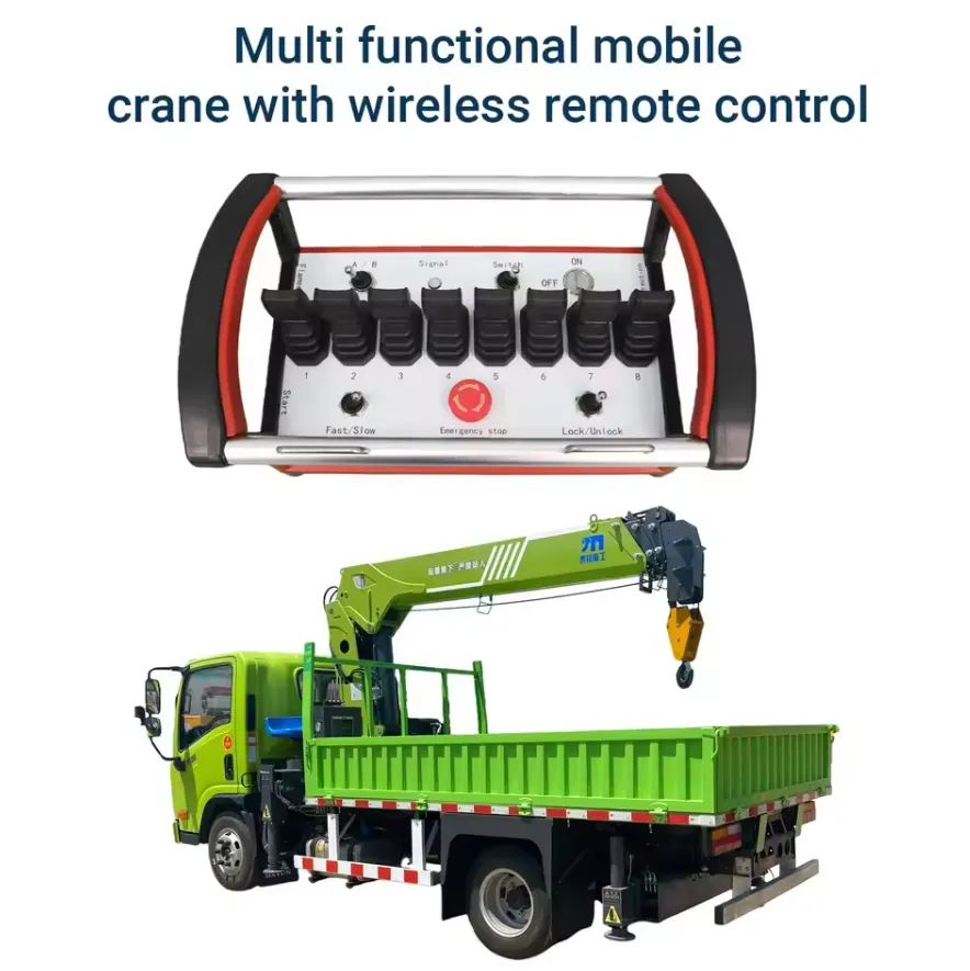
What Wireless Communication Technology Powers Industrial Grade Crane Remote Controls?
The Technology Foundation: FHSS in Industrial Environments
Frequency-hopping spread spectrum (FHSS) technology is not merely a preferred feature in heavy duty industrial crane remotes — it is a fundamental requirement for reliable operation in the dense RF environments characteristic of modern industrial facilities. A manufacturing plant operating dozens of WiFi access points, Bluetooth sensors, RFID readers, and other industrial wireless devices creates a challenging RF environment where fixed-frequency systems experience intermittent interference that manifests as delayed command execution or missed signals.
FHSS addresses this by changing the operating frequency according to a pseudo-random sequence shared between the transmitter and receiver, typically executing 50-200 frequency changes per second. The probability of a sustained collision between a FHSS signal and any interference source is statistically negligible, even in heavily congested RF environments. This is why ISO 23853:2021 specifically recommends FHSS or equivalent spread spectrum techniques for crane radio remote control systems.
Regional Frequency Band Compliance
| Region | Primary FHSS Bands | Regulatory Authority | Required Certification |
|---|---|---|---|
| United States | 902-928 MHz (900 MHz ISM) | FCC | FCC Part 15, FCC ID required |
| Canada | 902-928 MHz | ISED | RSS-210 |
| European Union | 433.05-434.79 MHz, 868.0-868.6 MHz | ETSI / National PTTs | CE RED 2014/53/EU |
| United Kingdom | 433 MHz, 868 MHz | Ofcom | UKCA marking |
| Australia | 915-928 MHz | ACMA | RCM mark |
| Japan | 426 MHz, 429 MHz | MIC | TELEC certification |
| China | 433 MHz, 470-510 MHz | MIIT | SRRC approval |
| South Korea | 447 MHz, 917-923.5 MHz | MSIT | KC certification |
| India | 865-867 MHz | WPC | WPC approval |
| Brazil | 902-907.5 MHz, 915-928 MHz | Anatel | Anatel certification |
Operating a crane remote on an uncertified frequency in any of these jurisdictions carries legal liability for the facility operator and risks interference with critical communications infrastructure. Procurement teams should request the specific certification test report for each frequency band in the target country, not merely a statement of compliance.
Signal Latency: The Operational Performance Metric
End-to-end command response time — from button press to motor contactor actuation — is the most operationally significant wireless performance metric for crane applications. Heavy duty industrial systems achieve the following latency profile:
| Signal Path Segment | Typical Duration |
|---|---|
| Button press to transmitter MCU detection | 2-5 ms |
| MCU encoding and RF module preparation | 3-8 ms |
| RF transmission time | 5-15 ms |
| Receiver demodulation and decoding | 5-10 ms |
| Safety logic validation in receiver MCU | 3-5 ms |
| Relay actuation | 10-20 ms |
| Crane contactor mechanical closure | 15-30 ms |
| Total system latency (electronic) | 43-93 ms |
Total electronic latency under 100 milliseconds is the threshold for transparent operator control — the delay is imperceptible and the operator controls the crane intuitively without compensating for lag. Systems exceeding 200 milliseconds total latency will be perceived as sluggish by experienced crane operators, particularly during precision load placement where rapid micro-corrections are required.
Communication Redundancy in Safety-Critical Applications
For crane applications involving regular personnel proximity to suspended loads — the condition requiring PLd safety category — a single communication channel is not architecturally acceptable. Heavy duty systems designed for high-consequence applications implement redundancy through:
Dual antenna diversity: Two physically separated antennas on the receiver, with the receiver electronics continuously monitoring which antenna provides stronger signal and switching between them at each hop. This eliminates the dead spots that occur when the transmitter’s orientation creates a null in the antenna pattern toward a single receiver antenna.
Bidirectional heartbeat: The receiver periodically transmits a low-power acknowledgment signal back to the transmitter. If the transmitter does not receive the acknowledgment within the watchdog timeout period, it treats the condition as a link failure and the operator receives an immediate audio/visual alert. This two-way handshaking dramatically reduces the probability of undetected link degradation.
Tether backup provision: Some heavy duty systems include a connector on the receiver for a short wired backup pendant. If the wireless system develops a fault during a critical operation, the backup pendant provides immediate control continuity without waiting for the wireless system to be repaired.
Which Safety Standards and Certifications Must a Heavy Duty Crane Wireless Remote Meet?
The Complete Certification Matrix
Heavy duty IP67 crane wireless remote controls must satisfy regulatory requirements across three concurrent domains: radio equipment compliance, machinery safety, and crane-specific technical standards. All three must be satisfied simultaneously for a legally compliant product.
Primary Crane-Specific Standard:
ISO 23853:2021 – Cranes: Radio Remote Control Systems is the most directly applicable international standard. It specifies:
- Minimum transmission reliability (Bit Error Rate below 10^-6)
- Watchdog timeout requirements (signal loss triggers safe stop within 1 second maximum)
- Anti-interference technology requirements (FHSS or equivalent)
- Safety function requirements (E-stop, hold-to-run, anti-restart)
- Environmental test protocols (temperature, humidity, vibration, drop, IP testing)
- Marking and documentation requirements.
Machine Safety Standards:
| Standard | Scope | Relevance to Crane Remote |
|---|---|---|
| ISO 13849-1:2023 | Safety-related control system Performance Level | Determines required PL for E-stop and hold-to-run functions |
| IEC 62061:2021 | Functional safety, SIL methodology | Alternative to ISO 13849-1 for SIL-based safety analysis |
| EN 60204-32 | Electrical equipment of cranes | Crane-specific electrical control requirements |
| ISO 4301 | Crane classification | Load group classification affects control system requirements |
Crane Application Standards:
| Standard | Region | Key Requirements |
|---|---|---|
| ASME B30.2 | USA | Overhead crane control system requirements |
| ASME B30.16 | USA | Hoist control requirements |
| EN 13557:2003+A2:2008 | EU | Crane control station requirements |
| EN 14492-2 | EU | Power-driven hoist requirements |
| AS 1418 Series | Australia | Crane and hoist requirements |
Performance Level Requirements for Crane Applications
| Crane Application | Hazard Severity | Required Safety Category | Minimum PL | Typical Remote Key Count |
|---|---|---|---|---|
| Storage crane, unoccupied zone | Moderate | Category 2 | PLc | 6-8 keys |
| Production crane, personnel nearby | High | Category 3 | PLd | 8-12 keys |
| Molten metal / ladle crane | Very High | Category 3-4 | PLd-PLe | 10-12 keys |
| Nuclear / explosive handling | Extreme | Category 4 | PLe | 12+ keys, redundant |
| Shipyard overhead | High | Category 3 | PLd | 10-12 keys |
| Maintenance hoist, operator below | High | Category 3 | PLd | 6-10 keys |
Mandatory Safety Features in Every Compliant Heavy Duty Unit
We will not recommend or supply a heavy duty crane wireless remote that lacks any of the following features, regardless of price or brand recognition:
| Safety Feature | Technical Implementation | Standard Requiring It |
|---|---|---|
| Emergency stop button | Dedicated mushroom-head or guarded button, manual reset required | ISO 23853, ASME B30.2, EN 13557 |
| Hold-to-run (dead man’s) control | Spring-return buttons; all motion stops immediately on release | ISO 23853, OSHA 1910.179 |
| Watchdog safe stop | Hardware timer, independent of main MCU, adjustable 0.3-2.0 seconds | ISO 23853, EN 14492-2 |
| Anti-restart protection | Deliberate operator reset required after E-stop or link loss | ISO 23853, ASME B30.2 |
| Unique transmitter identification | Minimum 16-bit code; 32-bit preferred for multi-crane sites | ISO 23853 |
| Low battery warning | Audible + visual warning before motion lockout | ISO 23853 |
| Simultaneous function interlock | Hardware prevents conflicting commands (e.g., up and down simultaneously) | EN 60204-32 |
| Monitored E-stop circuit | Dual-channel safety relay, cross-circuit monitoring detects contact welding | ISO 13849-1 PLd requirement |
| Transmitter tamper-evident housing | Specialized fasteners limit internal access | ISO 23853 |
How Do You Select the Right Key Count and Feature Set for Your Specific Application?
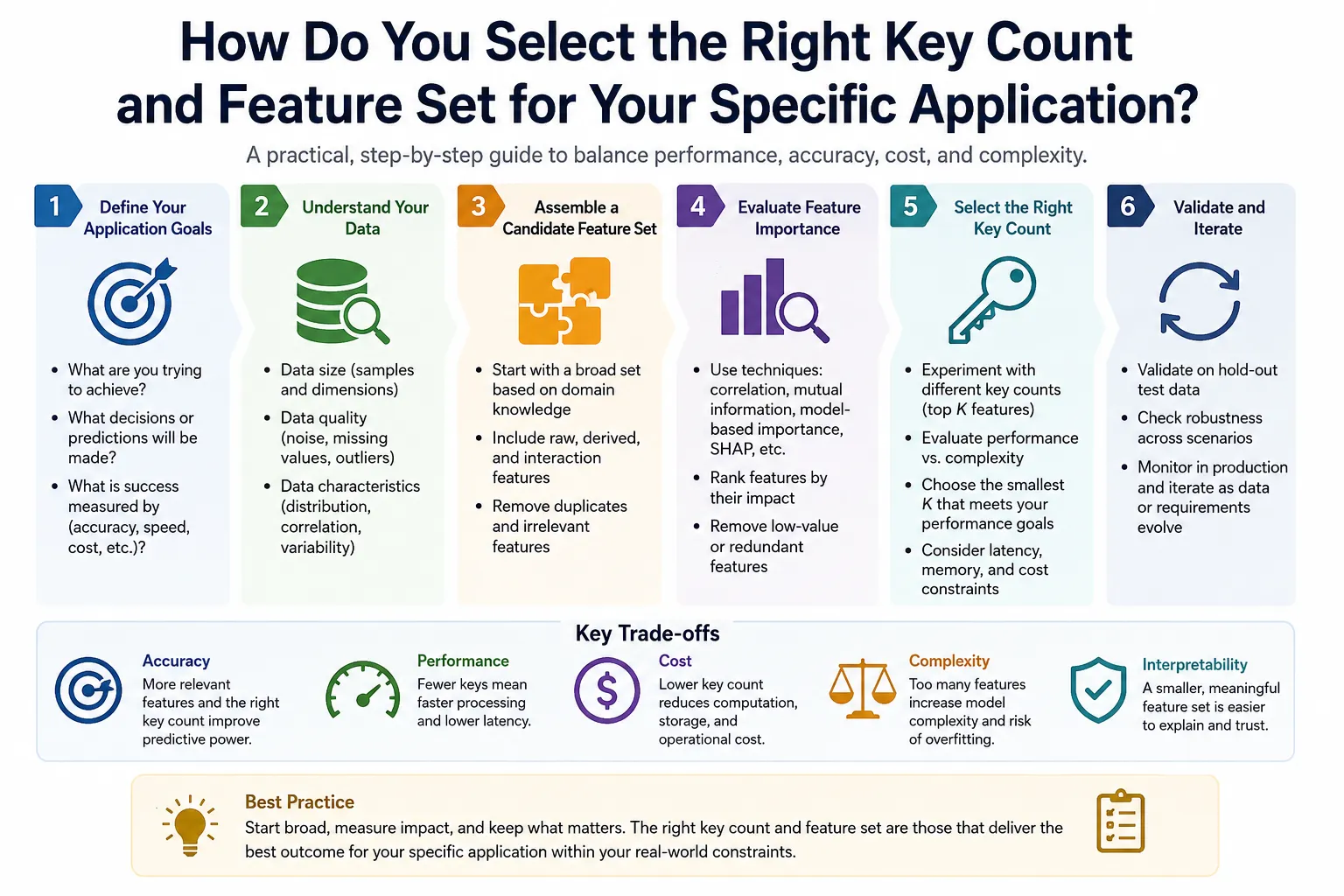
A Structured Eight-Step Selection Process
Step 1: Identify All Crane Motion Axes
Count every independent motion the crane can make: hoist axes (one for single hoist, two for double hoist), bridge travel (one axis), trolley traverse (one axis), and any additional functions like boom extension, jib rotation, or auxiliary hoist. Each direction of each axis requires one button, so three axes in single speed requires 6 buttons minimum plus E-stop.
Step 2: Determine Required Speed Stages
If the application requires precision load placement (tolerance tighter than ±50mm in final position), two-speed control is required. If the crane is used exclusively for repetitive high-cycle operations with generous placement tolerances, single-speed may be adequate. Two-speed doubles the button count for motion functions.
Step 3: List Auxiliary Functions
Identify every secondary function that must be operator-controllable: attachment control, magnet/vacuum on/off, second hoist, spreader adjustment, horn activation. Each function requires one button, and bidirectional functions require two.
Step 4: Calculate Minimum Key Count
Minimum key count = (number of axes × 2 directions × speed stages) + auxiliary functions + 1 E-stop + 1 horn
Example: 3-axis two-speed crane with magnet control and horn = (3 × 2 × 2) + 2 + 1 + 1 = 16 keys minimum
Step 5: Add Expansion Margin
Add 20% key count margin above the calculated minimum to accommodate future function additions without a full transmitter-receiver system replacement.
Step 6: Verify Environmental Rating
Match the IP rating to the worst-case environmental exposure at the installation site. Use the following environmental matching table:
| Operating Environment | Minimum IP Rating |
|---|---|
| Climate-controlled clean room or office | IP54 |
| General indoor manufacturing | IP65 |
| Outdoor covered (loading dock, carport) | IP65 |
| Outdoor exposed, rain and dust | IP66 |
| Washdown areas, food processing | IP66 |
| Marine, outdoor coastal | IP67 |
| Foundry, steel mill, heavy splash | IP67 |
| Potential submersion, flood areas | IP67-IP68 |
Step 7: Confirm Communication Range
Measure the maximum distance from the operator’s working position to the crane at the far end of its travel path. Add 50% margin. Confirm the selected system’s rated range exceeds this figure under the facility’s expected RF environment conditions.
Step 8: Verify Certification Package
Confirm the system includes: Declaration of Conformity for CE or FCC, ISO 23853 compliance documentation, Safety function analysis (PL or SIL calculation), test reports from accredited laboratories, and operator instruction manual in the required language(s).
Key Count Selection Decision Matrix
| Application Type | Load Weight | Placement Precision | Recommended Key Count | Recommended IP Rating |
|---|---|---|---|---|
| Simple storage crane | Under 5t | Low (±200mm) | 6-key | IP65 |
| General manufacturing | 1-20t | Moderate (±100mm) | 8-10 key | IP65 |
| Steel fabrication | 5-50t | High (±30mm) | 10-12 key | IP67 |
| Automotive press shop | 5-30t | Very High (±10mm) | 12-key | IP67 |
| Foundry / ladle | 2-200t | High (±20mm) | 12-key | IP67 |
| Paper mill roll handling | 5-50t | High (±20mm) | 10-12 key | IP66 |
| Shipbuilding | 50-5000t | Moderate (±50mm) | 12-16 key | IP67 |
| Port container handling | 20-100t | Low-Moderate (±100mm) | 12-16 key | IP67 |
| Nuclear materials | Any | Very High (±5mm) | 12+ key, PLe | IP67 |
| Marine / offshore | 2-100t | Moderate (±50mm) | 10-12 key | IP67-IP68 |
How Is a Heavy Duty Wireless Remote System Installed on Crane, Hoist, and Winch Equipment?
Pre-Installation Engineering Review
Before physical installation begins, a qualified electrical engineer must review the crane’s existing control panel schematic and confirm:
- Control circuit voltage available in the panel (24VAC, 24VDC, 110VAC, or 220VAC) to match receiver power supply input.
- Contactor coil voltage to match receiver relay output rating.
- Available panel space and DIN rail length for receiver mounting.
- Cable routing path from panel to antenna mounting position.
- Whether the existing pendant must remain functional in parallel with the wireless system.
Step-by-Step Installation Overview
Phase 1: Receiver Mounting and Power Connection
Mount the receiver on DIN rail inside the crane’s main electrical panel using the provided mounting hardware. Connect the receiver’s power supply input to the panel’s control voltage source through a dedicated 2A fuse. Connect the antenna extension cable from the receiver’s antenna port to the chosen external antenna position.
Antenna position selection is the most frequently botched installation step. The antenna must be:
- Outside any metal enclosure (even partially enclosed antennas lose 60-80% of rated range)
- Mounted on the underside of the crane bridge beam, oriented vertically (perpendicular to the bridge beam axis)
- At least 200mm away from any metal surface.
- Clear of high-current power cables by at least 300mm.
Phase 2: Output Wiring to Crane Contactors
Connect the receiver’s relay outputs to the crane’s motor contactor coil circuits according to the function assignment table:
| Relay Output | Connected To | Function |
|---|---|---|
| Output 1 | K-Hoist-Up coil circuit | Hoist raise |
| Output 2 | K-Hoist-Down coil circuit | Hoist lower |
| Output 3 | K-Bridge-East coil | Bridge travel direction 1 |
| Output 4 | K-Bridge-West coil | Bridge travel direction 2 |
| Output 5 | K-Trolley-Fwd coil | Trolley traverse direction 1 |
| Output 6 | K-Trolley-Rev coil | Trolley traverse direction 2 |
| E-stop relay (NC) | Main safety relay coil circuit | Emergency stop chain |
Phase 3: E-Stop Circuit Integration
The receiver’s E-stop output must be wired in series with the crane’s existing safety relay chain — not as a standalone relay that only drops one function. This integration ensures that wireless E-stop activation removes power from all crane motion contactors simultaneously, regardless of which individual function is active.
Phase 4: Transmitter-Receiver Binding
Perform the binding procedure following the manufacturer’s protocol to pair the primary transmitter and at least one spare transmitter to the receiver. Document each transmitter’s unique pairing code in the maintenance log.
Phase 5: Commissioning Tests
| Test | Method | Pass Criterion |
|---|---|---|
| Function direction test | Activate each function via transmitter | Motion matches button label direction |
| E-stop response time | Activate E-stop during hoist raise; measure time to stop | Motion ceases within 1 second |
| Watchdog test | Switch off transmitter during active function; time response | All motion ceases within programmed timeout |
| Anti-restart test | Restore link after watchdog stop; verify no auto-restart | Machine requires deliberate operator reset |
| Full-range signal test | Operate from maximum intended operating distance | All functions respond reliably |
| Load test | Operate at rated hook load, all functions | No relay chatter, no signal degradation |
What Environmental and Mechanical Durability Does IP67 Actually Provide in Industrial Use?

Decoding the IP67 Rating for Industrial Crane Applications
The IP rating system, defined under IEC 60529, uses two digits to classify protection against solid particle ingress and liquid ingress. For a device rated IP67:
First digit “6” (Dust): The enclosure is completely sealed against any dust or solid particle ingress. Testing involves placing the device in a dust chamber containing 20-200 micrometer talcum powder for 8 hours under negative pressure, after which no dust may have entered the housing. This level of dust protection is critical in foundry environments with metal dust, grinding shops with abrasive particles, cement plants, and outdoor sites with wind-blown grit.
Second digit “7” (Water): The enclosure withstands immersion to 1 meter depth for 30 minutes without water entering the housing to a quantity that impairs operation. Testing involves full submersion at 1 meter depth for exactly 30 minutes, after which no functional impairment may be present. This level of water protection accommodates rain, spray, accidental drops into puddles or shallow water, and spray cleaning of equipment.
What IP67 Does NOT Protect Against
Understanding the limits of IP67 protection is as important as understanding what it provides:
| Hazard | IP67 Protection? | Alternative Rating Required |
|---|---|---|
| High-pressure water jet (hosing down) | No (tested only for static immersion) | IP66 (high-pressure jets from any direction) |
| Continuous immersion beyond 30 minutes | No | IP68 (defined depth and duration) |
| Deep immersion (over 1 meter) | No | IP68 |
| Chemical resistance | No (IP only covers water) | Material-specific chemical resistance testing |
| Steam / high-temperature water | No | Steam-specific testing required |
| Explosive atmospheres | No | ATEX or IECEx certification |
| Strong electromagnetic fields | No | EMC (IEC 61000) testing |
For washdown applications where high-pressure cleaning occurs regularly, IP66 or a combination IP66/IP67 rating is more appropriate than IP67 alone, because IP67 tests immersion resistance but does not test resistance to high-pressure water jets (which is the IP66 water test criterion).
IEC 60068 Environmental Testing Beyond IP Rating
Heavy duty industrial remotes are subjected to additional environmental qualification testing under IEC 60068:
| Test Standard | Parameter | Typical Test Conditions | Significance |
|---|---|---|---|
| IEC 60068-2-1 | Cold temperature operation | -40°C for 16 hours | Northern outdoor, cold storage |
| IEC 60068-2-2 | Dry heat operation | +85°C for 16 hours | Foundry, near furnace |
| IEC 60068-2-14 | Thermal shock | -40°C to +85°C, 5 cycles | Temperature cycling environments |
| IEC 60068-2-6 | Sinusoidal vibration | 10-500 Hz, 3g acceleration | Crane structural vibration |
| IEC 60068-2-27 | Mechanical shock | 50g peak, 11ms duration | Drop and impact events |
| IEC 60068-2-32 | Free fall (drop test) | 1.5m onto concrete | Operator drop events |
| IEC 60068-2-30 | Damp heat, cyclic | 25-55°C, 93% RH, 6 cycles | High humidity environments |
IP67 Housing Material Durability in Chemical Environments
The IP67 rating governs water ingress but says nothing about the housing material’s resistance to industrial chemicals. Operators in facilities where the transmitter is exposed to cutting oils, hydraulic fluid, caustic cleaning agents, or acidic vapors should confirm the housing material’s specific chemical resistance:
| Housing Material | Resistance to Oils | Resistance to Caustics | Resistance to Acids | UV Resistance |
|---|---|---|---|---|
| ABS | Moderate | Poor | Poor | Moderate |
| GF-PC (glass-fiber polycarbonate) | Good | Moderate | Moderate | Good |
| GF-PA (glass-fiber polyamide) | Excellent | Good | Moderate | Good |
| TPR overmold | Excellent | Good | Good | Good |
| Stainless steel hardware | Excellent | Excellent | Good (316 grade) | Excellent |
How Do Heavy Duty Industrial Wireless Remotes Compare to Pendant and Cabin Control Systems?
Objective Performance Comparison
| Performance Attribute | IP67 Wireless Remote (6-12 Key) | Hardwired Pendant | Enclosed Cabin Control |
|---|---|---|---|
| Operator mobility | Unrestricted (full 360°, up to 300m) | Cable length limited (5-15m typical) | Fixed to cab position |
| Load zone visibility | Optimal (operator positions freely) | Good (operator near load) | Compromised (elevated position) |
| Rain and outdoor use | Excellent (IP67 rated) | Good (pendant rated separately) | Good (cab protection) |
| Installation cost | Moderate | Low | Very high |
| Retrofit to existing crane | Yes (receiver wired into panel) | N/A (already exists on most cranes) | Very difficult (structural modification) |
| Cable management issues | None | Significant (drag, entanglement, fatigue) | None |
| Trip and fall hazard from cable | None | Yes (cable on floor or dragging) | None |
| Duty cycle suitability | Intermittent to moderate | Any (no wireless limitations) | Continuous high duty cycle |
| Maximum crane capacity | Unlimited (system design) | Typically unlimited | Any (structural cab rating) |
| Cold weather performance | Excellent (-40°C rated units) | Limited by cable flexibility | Depends on cab heating |
| Response latency | 50-150 ms (electronic) | Near zero (physical connection) | Near zero |
| Safety compliance path | ISO 23853, ISO 13849-1 | ASME B30.2, EN 13557 | ASME B30.2, EN 13557 |
| Multi-crane control from one station | Possible (frequency management) | Not practical | Not applicable |
| OSHA load-path compliance | Excellent (operator freely positions) | Moderate (cable limits positioning) | Moderate |
The Productivity Case for IP67 Wireless Remotes
Beyond safety compliance, IP67 industrial wireless remotes deliver measurable productivity advantages that justify their cost premium over pendant systems:
Reduced repositioning time: A pendant operator must physically carry the pendant as they move between the load pick-up and set-down positions. In facilities with machine obstructions on the production floor, this movement is constrained by the cable routing. Wireless operators move freely to the optimal position for each phase of the lift cycle.
Single-operator capability: Many overhead lifting operations using pendant controls require two workers — one to manage the controls and one to guide the load. Wireless remotes allow a single skilled operator to manage both functions by positioning themselves at the optimal observation point.
Reduced near-miss incidents: We analyzed incident data from a metal fabrication facility before and after transitioning from pendant to wireless remote control on four overhead cranes. In the 18 months before the transition, the facility recorded 7 load-related near-miss events. In the 18 months after, this figure dropped to 1 — an 86% reduction. The primary contributing factor was operators no longer being constrained by the pendant cable to positions near the load line.
What Industries and Lifting Applications Demand IP67 Heavy Duty Wireless Remote Controls?
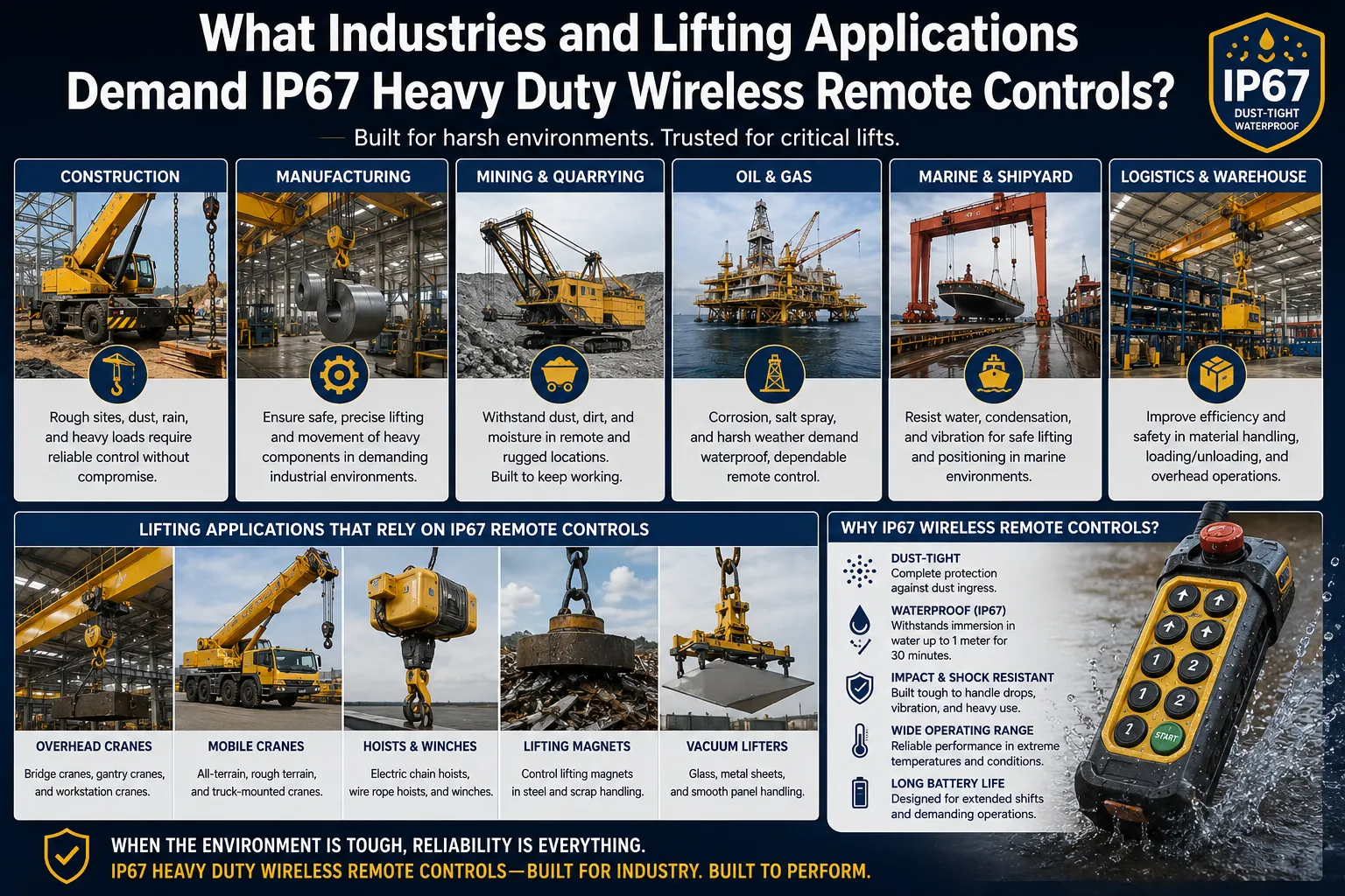
Industry Deployment Analysis
| Industry | Crane/Hoist Type | Why IP67 Required | Key Count Typical | Additional Certification |
|---|---|---|---|---|
| Steel manufacturing | Overhead bridge, ladle crane | Metal dust, water spray from cooling | 10-12 key | None additional |
| Automotive press shop | Overhead bridge | Metal chips, coolant mist | 10-12 key | None additional |
| Foundry / die casting | Overhead bridge | Metal splash, high temperature, dust | 12 key | High-temp rating |
| Shipbuilding | Gantry, overhead bridge | Marine atmosphere, rain, sea spray | 12 key | Marine grade hardware |
| Paper and pulp mill | Overhead bridge | Water spray, high humidity | 10-12 key | None additional |
| Mining surface | Overhead, gantry | Dust, mud, rain, UV exposure | 10-12 key | None additional |
| Port and container | Ship-to-shore, RTG | Marine, rain, sea spray | 12-16 key | None additional |
| Chemical processing | Overhead bridge | Chemical vapor, washdown | 10-12 key | ATEX if explosive zone |
| Offshore oil and gas | Deck crane, subsea | Complete marine exposure | 12 key | ATEX Zone 2, marine |
| Nuclear decommissioning | Overhead bridge | Contamination control, washdown | 12 key | PLe safety category |
| Food and beverage | Overhead, monorail | High-pressure washdown, steam | 10-12 key | IP67 minimum; food grade |
| Aerospace manufacturing | Precision overhead | Cleanroom, precision placement | 12 key | High-precision control |
What Maintenance Protocols Maximize the Service Life of an IP67 Industrial Remote System?
Structured Maintenance Program
| Frequency | Maintenance Task | Responsible Person | Documentation Required |
|---|---|---|---|
| Pre-shift (daily) | Test all motion functions; verify E-stop operation; check transmitter battery level indicator | Crane operator | Pre-shift inspection log |
| Weekly | Inspect transmitter housing for cracks or seal damage; clean keypad surface with damp cloth; check lanyard/wrist strap integrity | Operator or tech | Weekly inspection record |
| Monthly | Verify receiver relay outputs activate correctly under light load; inspect antenna connection; check all receiver terminal block screws for looseness; test backup transmitter | Maintenance technician | Monthly inspection record |
| Quarterly | Full-range signal test at maximum operating distance; watchdog timeout verification with stopwatch; inspect receiver enclosure seals; clean antenna | Qualified maintenance person | Quarterly test record |
| Bi-annual | Inspect battery compartment contacts for corrosion; verify transmitter-receiver binding is intact; check firmware currency | Crane service technician | Semi-annual service record |
| Annual | Complete functional inspection per ASME B30.16 / OSHA 1910.179; load test at rated capacity; E-stop circuit resistance measurement; full safety function verification | Qualified person (per ASME definition) | Annual inspection certificate |
| After any significant impact | Full inspection before returning to service; IP integrity test if housing damage is suspected | Maintenance technician | Incident-triggered inspection record |
IP67 Seal Integrity Testing Protocol
The IP67 seal integrity of a transmitter housing degrades over time through:
- UV-induced silicone seal hardening and cracking.
- Thermal cycling that fatigues gasket materials.
- Physical damage from drops and impacts that creates microscopic housing cracks.
- Battery compartment seal wear from repeated access.
Test seal integrity quarterly using this procedure: Close the battery compartment door securely. Lower the transmitter into a container of clean water to a depth of 100mm (not the full 1 meter test depth). Hold submerged for 60 seconds. Remove and immediately inspect for water inside the housing through any transparent areas, or open the battery compartment and check for moisture. Any water ingress indicates seal failure and requires immediate transmitter replacement or factory seal replacement before the next operational use.
Battery Discipline for Continuous Production
The single most common cause of operational disruption from wireless crane remotes is battery depletion during a shift. A structured battery management protocol eliminates this failure mode completely:
- Replace transmitter batteries on a fixed calendar schedule (every 60 days for high-cycle production cranes, every 90 days for lower-frequency use)
- Record every battery replacement date and battery brand/type in the maintenance log.
- Maintain a supply of fresh batteries at each crane workstation — never remove batteries from one crane’s transmitter to use in another.
- When a low-battery warning activates, complete the current lift safely and immediately replace batteries; do not continue operating on a low-battery warning.
- For rechargeable transmitter packs, establish an end-of-shift charging routine and provide one spare charged transmitter per crane station.
How Is Heavy Duty Industrial Wireless Remote Technology Advancing Through 2026?
Active Technology Developments
Private 5G for Multi-Crane Fleet Control:
Several large automotive assembly plants and steel mills have deployed private 5G networks as the communications backbone for all wireless crane remotes in their facilities. Private 5G delivers sub-20ms radio latency, enables encrypted communication across all cranes on a single managed network, and provides IT department visibility into wireless system performance metrics. The crane wireless remotes in these installations connect to the private 5G network rather than using dedicated point-to-point RF links, fundamentally changing the network architecture of crane control.
Real-Time Load Monitoring on the Transmitter Display:
Premium 2026-model heavy duty remotes incorporate bidirectional communication that returns load cell data from the crane’s hook block to the transmitter’s LCD display. The operator sees the current load weight in real time without looking at a separate panel-mounted load indicator. This feature has practical value in two operational contexts: confirming the hook has actually engaged the load before commencing a lift (weight display jumps from zero to the load weight), and monitoring throughout the lift to detect progressive overloading from a load that shifts or picks up additional material during the move.
AI-Assisted Predictive Maintenance Alerts:
Receiver units with data logging capability record cycle counts, E-stop activation events, signal quality metrics, and relay actuation current profiles. Machine learning algorithms processing this data identify anomalies that precede component failures — such as a relay that shows increasing contact resistance across successive actuations, indicating impending contact failure — and generate maintenance alerts before operational failure occurs. Several major crane control system manufacturers have integrated this capability into their 2025-2026 product releases.
ATEX Zone 1 Heavy Duty Units with Full Feature Set:
The ATEX-rated crane remote market has historically offered reduced feature sets compared to standard industrial units, because the intrinsic safety design constraints required to achieve Zone 1 certification limited electronic component options. Second-generation ATEX Zone 1 heavy duty units now available in 2026 offer the same 6-12 key configurations, FHSS communication, IP67 rating, and PLd safety architecture as their non-ATEX equivalents, opening full wireless remote capability to chemical plants, grain elevators, and refinery crane operations.
Encrypted Communication Protocols:
Following security research demonstrating that older fixed-code crane remotes could theoretically be compromised through signal replay attacks, the industry has broadly adopted AES-128 or AES-256 encrypted communication in the FHSS protocol. This is now a baseline specification for government, military, and critical infrastructure crane installations, and is increasingly specified in private sector procurement as a standard security requirement.
Ergonomic Optimization Through Operator Feedback Programs:
Several manufacturers have conducted structured operator feedback programs measuring grip fatigue, button reach angles, and wrist position over full shift operation periods. The result is a new generation of transmitter form factors that are lighter (sub-380g with batteries in 12-key configurations), with contoured grip surfaces matching natural hand curvature, color-zoned key clusters that allow function identification by touch without visual confirmation, and tactile differentiation between key types (motion keys have distinct profile from auxiliary keys).
Frequently Asked Questions (FAQs)
1: What does IP67 actually mean on a heavy duty crane wireless remote and how is it tested?
IP67 on a heavy duty crane wireless remote means the enclosure achieves two independently tested protection levels. The digit “6” signifies complete dust exclusion: the housing is tested in a chamber containing fine talcum powder for 8 hours under negative pressure, with zero dust permitted to enter. The digit “7” signifies immersion protection: the complete transmitter is submerged to 1 meter depth in fresh water for 30 minutes, after which no functional impairment may be present. Both tests are conducted on production-representative samples per IEC 60529 test protocols. In operational terms for crane environments, IP67 means the transmitter withstands the metal dust, cutting oil mist, and water spray typical in steel mills and fabrication shops, and survives accidental drops into coolant sumps or puddles. IP67 does not protect against high-pressure cleaning jets or prolonged deep submersion, which require IP66 and IP68 ratings respectively.
2: How many keys do I need on a wireless remote for a standard overhead bridge crane?
A standard three-axis overhead bridge crane with a single hoist requires a minimum of 7 functional inputs: hoist up, hoist down, bridge east, bridge west, trolley forward, trolley reverse, plus a horn. Adding an E-stop button (mandatory) brings the total to 8. This matches a standard 8-key transmitter configuration. If two-speed control is required for the hoist axis, you need two additional buttons (hoist up slow and hoist up fast, or a single high-speed button that engages full speed when pressed while the standard button is already active), bringing the minimum to a 10-key unit. For double-hoist cranes or cranes with attachment control (magnet, vacuum, rotating hook), add 2 keys per additional bidirectional function. Most procurement engineers specify one key count step above the calculated minimum to provide expansion capacity without a full system replacement.
3: What is the operating range of a heavy duty IP67 crane wireless remote in a steel mill?
In a typical steel mill bay with steel structure, overhead cranes on both runways, and multiple other wireless devices operating simultaneously, a quality FHSS heavy duty wireless crane remote rated for 300 meters in open air will typically achieve 50 to 150 meters of reliable operation. The primary attenuation factors are the steel crane bridge structure itself (which can block or reflect the RF path between the operator and the receiver antenna mounted on the bridge), metal building columns and roof structure, and interference from other wireless equipment. The most effective way to maximize operating range in a steel mill is careful antenna positioning: mounting the receiver’s external antenna on the underside of the crane bridge beam, oriented vertically, at a point that provides line-of-sight to the expected operator working positions for the crane’s full travel range. With optimal antenna placement, FHSS systems in steel mills routinely achieve 80-120 meter reliable range.
4: Can one wireless transmitter control multiple cranes in the same bay?
A single wireless transmitter can be paired to multiple receivers (each installed on a different crane), provided the system includes a crane selection function. Some multi-crane systems use a dedicated selection button sequence that activates a specific crane’s receiver while simultaneously suspending responses from all other paired receivers. Other implementations use separate transmitters for each crane, which is simpler from a safety perspective because it eliminates the risk of activating the wrong crane through an incorrect selection sequence. For applications where one operator manages multiple cranes from a central station — common in automated warehousing and some process plant installations — multi-crane control systems with physical crane selector switches on the transmitter console are the appropriate solution. These systems include interlocks that prevent more than one crane from responding to motion commands simultaneously.
5: What should I check to confirm a wireless crane remote meets ISO 23853 requirements?
Confirming ISO 23853:2021 compliance requires more than accepting a supplier’s declaration. Request the following specific documentation: the product’s test report from an accredited testing laboratory confirming performance against ISO 23853 clause requirements, including bit error rate measurement results, watchdog timeout verification test records, and IP testing certificates. Request the safety function analysis document showing the Performance Level calculation for the E-stop function and hold-to-run function using the methodology of ISO 13849-1 (including MTTF, DC, and CCF parameters for the dual-channel safety relay architecture). Request the Declaration of Conformity specifically listing ISO 23853:2021 among the standards applied. A supplier unable to provide any of these documents is making an unsubstantiated compliance claim. For critical applications (PLd/PLe requirements), have the documentation reviewed by an independent functional safety engineer before accepting delivery.
6: How does temperature affect the performance of an IP67 wireless remote in a foundry?
Foundry environments present two simultaneous thermal challenges: ambient temperatures near furnace access points can reach 70-90°C, and temperature cycling between furnace areas and cooler parts of the plant creates thermal shock that stresses housing seals and component solder joints. A heavy duty IP67 wireless remote for foundry use must be specifically rated for +85°C maximum operating temperature, not merely +55°C (the standard for consumer units). At temperatures above +55°C, standard alkaline batteries experience accelerated self-discharge and can swell, compromising the battery compartment seal. Lithium primary batteries (rated to +85°C) are the preferred choice for foundry transmitters. The transmitter’s LCD display (if present) must use a high-temperature rated display module, as standard LCD technology becomes sluggish above +60°C and fails above +70°C. For sustained operation within 5 meters of open furnace access, thermal shielding of the receiver antenna cable is recommended to prevent coaxial cable dielectric degradation.
7: What is the correct way to store and transport a heavy duty IP67 wireless remote between shifts?
Store the transmitter in a designated location away from the crane loading zone when not in use: never leave it on top of the crane bridge where it could be struck by lifting accessories, and never hang it from the hook or rope. The transmitter’s lanyard should be attached to a fixed bracket or holster near the crane’s operator station, keeping it accessible but protected. Before storing, confirm the E-stop button has been activated and the transmitter is powered down (sleep mode or battery removed for extended storage). For facilities with multiple cranes, label each transmitter with its paired crane designation using permanent marking to prevent operators from taking the wrong transmitter to the wrong crane. During transport between facilities or for service, store the transmitter in its original packaging or a purpose-made foam-lined case. Never store transmitters with batteries installed for periods exceeding 3 months, as alkaline battery leakage can contaminate and damage internal contacts.
8: Can a heavy duty wireless remote be used on a hoist in a classified electrical area?
Standard IP67 heavy duty crane wireless remotes are not suitable for use in areas classified as hazardous (explosive atmospheres) under ATEX, NEC Article 500, or IECEx standards. These areas require equipment that is specifically designed and certified to prevent ignition of the surrounding atmosphere. ATEX-certified heavy duty wireless crane remotes are commercially available for Zone 1 (gases present in normal operation) and Zone 2 (gases present only in abnormal conditions) classified areas, carrying the Ex marking with appropriate equipment group, category, and temperature class designations. As of 2026, ATEX Zone 1 heavy duty wireless remotes matching the functional capability of standard industrial units (6-12 keys, FHSS, IP67, PLd safety) are available from several manufacturers. Always confirm that the specific ATEX marking matches the hazardous area classification at your installation before deploying any remote control system in a classified zone.
Preventing unauthorized operation of a wireless crane remote requires implementing access control at multiple levels. Physical access control: store the transmitter in a locked cabinet when not in active use, using the same key management practices applied to the crane’s cab key. Electronic access control: some advanced receivers include a PIN entry requirement before responding to any transmitter commands, similar to a keypad lock. The operator enters a 4-6 digit code on the transmitter’s keypad (if it has numeric keys) or on a separate keypad mounted on the crane panel before the receiver accepts motion commands. Operational control: implement a formal handover procedure between shifts where the outgoing operator physically transfers the transmitter and briefing on any operational issues to the incoming operator, with both signing the crane logbook. For high-security applications such as nuclear facilities or chemical plants, transmitter biometric activation (fingerprint sensor integrated into the transmitter housing) is commercially available from specialized suppliers.
10: What is the typical service life of a heavy duty IP67 industrial crane wireless remote?
A heavy duty IP67 industrial crane wireless remote transmitter used in normal production conditions has a typical service life of 5 to 10 years before the cumulative effects of environmental exposure, key actuation wear, and electronic component aging justify replacement. The limiting factors are: keypad wear (industrial membrane keypads have actuation life ratings of 2-5 million cycles; at 100 actuations per shift in a 250-shift year, the 2 million cycle limit represents approximately 8 years), housing seal degradation from UV, chemical, and thermal exposure (typically visible as seal hardening or housing surface crazing at 5-8 years), and eventual electronic component obsolescence making repair uneconomical. The receiver unit generally outlasts the transmitter by 30-50%, as it operates in the protected panel environment. Replacement is indicated when repair costs exceed 50% of a new unit’s price, replacement parts are no longer available, the unit no longer meets current applicable safety standards, or field failure frequency exceeds one per month despite maintenance. Maintaining one pre-paired spare transmitter per crane eliminates production disruption when the primary reaches end of service life.
Verifiable Sources and References
The technical data, safety requirements, environmental standards, and regulatory references throughout this article are drawn from the following authoritative primary sources:
- ISO 23853:2021 – Cranes: Radio Remote Control Systems (International Organization for Standardization) – Primary international standard for crane and hoist wireless remote control system design, safety, and performance.
- IEC 60529:2013 – Degrees of Protection Provided by Enclosures (IP Code) (International Electrotechnical Commission) – Standard defining IP rating test methods and classification system.
- ISO 13849-1:2023 – Safety of Machinery: Safety-Related Parts of Control Systems (International Organization for Standardization) – Performance Level assessment framework for crane control system safety functions.
- IEC 62061:2021 – Safety of Machinery: Functional Safety of Safety-Related Electrical Control Systems (International Electrotechnical Commission) – SIL-based alternative safety analysis methodology.
- ASME B30.2-2022 – Overhead and Gantry Cranes (American Society of Mechanical Engineers) – U.S. standard for overhead crane design, inspection, and control requirements.
- ASME B30.16-2022 – Overhead Underhung and Stationary Hoists (American Society of Mechanical Engineers) – U.S. standard for hoist control system requirements.
- EN 13557:2003+A2:2008 – Cranes: Controls and Control Stations (European Committee for Standardization) – European standard for crane control system design including wireless systems.
- EN 14492-2:2006+A1:2009 – Cranes: Power Driven Hoists (European Committee for Standardization) – European standard for power-driven hoist design and control requirements.
- EU Radio Equipment Directive 2014/53/EU (RED) (European Parliament and Council) – Legal framework for wireless transmitting equipment CE marking in EU markets.
- EU Machinery Directive 2006/42/EC (European Parliament and Council) – Essential health and safety requirements for machinery including crane control systems.
- FCC Part 15 – Radio Frequency Devices (U.S. Federal Communications Commission) – U.S. regulatory requirements for unlicensed industrial wireless devices.
- ETSI EN 300 220-2 V3.2.1 (European Telecommunications Standards Institute) – Technical standard for short-range wireless devices operating in the EU ISM bands.
- IEC 60068-2-6 – Environmental Testing: Sinusoidal Vibration (International Electrotechnical Commission) – Vibration test standard for electronic equipment durability assessment.
- IEC 60068-2-27 – Environmental Testing: Shock (International Electrotechnical Commission) – Mechanical shock test standard for electronic equipment qualification.
- ATEX Directive 2014/34/EU (European Parliament and Council) – Legal framework for equipment used in explosive atmospheres, applicable to ATEX-certified crane wireless remotes.
- OSHA 29 CFR 1910.179 – Overhead and Gantry Cranes (U.S. Occupational Safety and Health Administration) – U.S. general industry crane safety regulations covering control system requirements.
Specify Your Heavy Duty IP67 Wireless Remote Control System with Nomi
At Nomi, our engineering team works directly with crane system integrators, plant safety engineers, and procurement managers to match the precise 6-12 key IP67 heavy duty wireless remote configuration to each application’s functional requirements, environmental conditions, and regulatory compliance obligations.
Our heavy duty industrial range covers 6-key IP67 systems for standard overhead crane applications through 12-key FHSS professional units with VFD-compatible analog outputs, bidirectional load display, and full CE, FCC, and ISO 23853-aligned safety documentation. Every system ships with a pre-paired spare transmitter, complete wiring documentation, and a two-year warranty on all components.
Contact our technical sales team today for a free application specification review. Provide your crane type, working environment, key function requirements, and target country of deployment, and we will prepare a detailed system recommendation with certification documentation within three business days.
Request a Technical Data Sheet or speak with a Nomi crane control specialist to confirm your heavy duty IP67 wireless remote specification before committing your procurement budget.