

Joystick Remote Controls
Products
PRODUCTS
CONTACT US
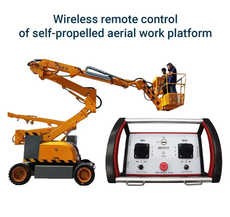

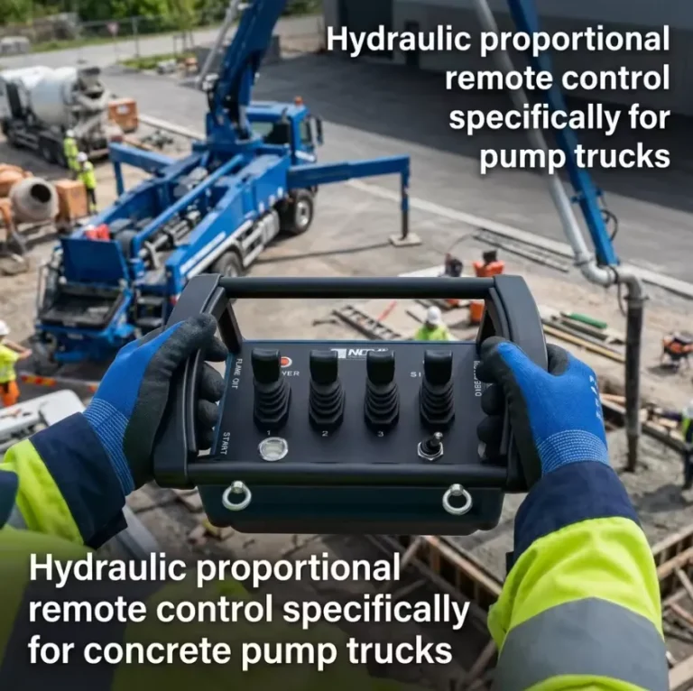
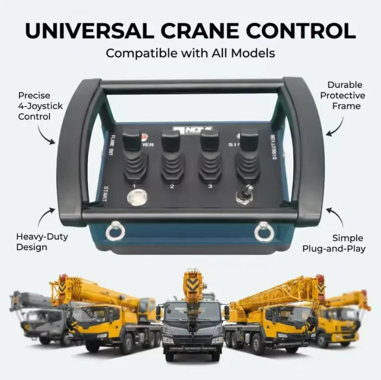
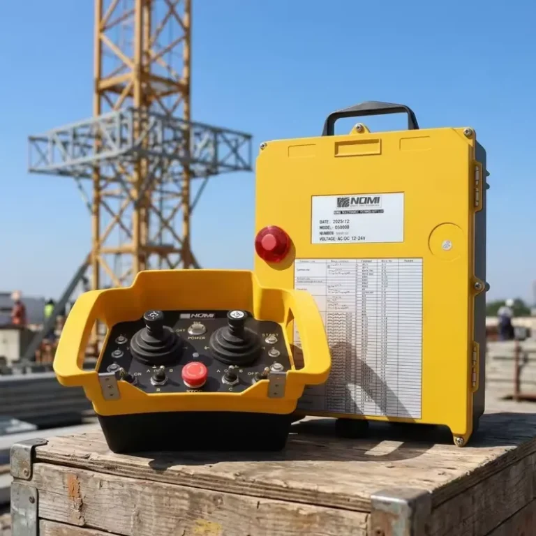
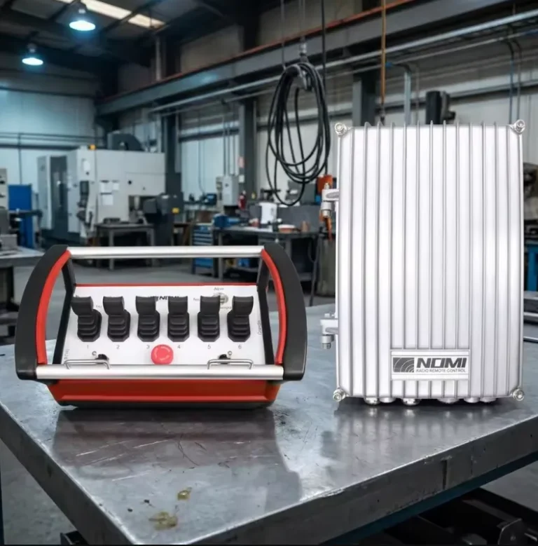
Industrial joystick remote controls with wireless precision transmission are the definitive solution for proportional speed control in cranes, excavators, marine vessels, and heavy machinery where push-button step control creates unacceptable load shock or positioning error. Wireless joystick systems operating at 868 MHz or 915 MHz FHSS deliver command latency below 80 milliseconds, proportional resolution of 8 to 12 bits, and operating ranges up to 300 meters with certified SIL 2 or Performance Level d safety architectures. At Nomi, we specify and supply these systems across demanding applications globally, and this guide consolidates what engineers and buyers need to know.
What Is an Industrial Joystick Remote Control and How Does It Differ From Push-Button Systems?
An industrial joystick remote control is a wireless transmitter device that converts continuous mechanical deflection of one or more joystick axes into proportional analog or digital signals, transmitted by radio frequency to a receiver that outputs corresponding control signals to actuators, drives, or hydraulic valves. Unlike push-button remotes that deliver discrete on/off commands at fixed speed steps, joystick systems provide continuous, proportional control across the full range of motion from zero to maximum speed or pressure.
This proportional capability is the defining characteristic that separates joystick remotes from button-based systems, and it matters enormously in applications where smooth, graduated machine response directly affects load safety, product quality, or operational efficiency. A crane operator lowering a precision glass panel into a production line, an excavator operator grading a slope to millimeter tolerances, or a marine crane operator transferring cargo in sea swell all require control inputs that match the subtlety of the task, and push-button step control cannot deliver that subtlety.
The global market for industrial wireless joystick remote controls was valued at approximately USD 780 million in 2023 and is projected to reach USD 1.4 billion by 2030 at a compound annual growth rate (CAGR) of 8.7%, driven by automation investment, safety regulation tightening, and the replacement of aging tethered control systems, according to MarketsandMarkets Research (Industrial Wireless Remote Control Market Report, 2023). This growth trajectory reflects the broadening adoption of proportional wireless control across industries that previously relied on mechanical linkages, hydraulic levers, or hardwired proportional controllers.
At Nomi, we work with facilities making this transition every quarter, and the consistent finding is that operators trained on joystick wireless systems achieve load placement accuracy two to three times better than operators using the best push-button step control systems, measured by positional error at the target location.
Joystick vs. Push-Button: Core Capability Comparison
| Capability | Push-Button Remote | Joystick Remote | Impact on Operations |
|---|---|---|---|
| Speed control type | Discrete steps (2–4 levels) | Continuous proportional (0–100%) | Joystick enables smooth acceleration without load shock |
| Positioning precision | Limited by step size | Limited by operator skill and resolution | Joystick achieves 3–10x better placement accuracy |
| Load sway generation | High (step changes excite pendulum) | Low (smooth ramp control reduces excitation) | Joystick reduces load swing by 60–80% |
| Operator fatigue | Low (simple button press) | Moderate (continuous grip and deflection) | Ergonomic design critical for joystick systems |
| Training time | 1–2 hours | 4–8 hours | Joystick requires proportional skill development |
| Cost (system) | $1,200–$4,500 | $2,500–$12,000 | Joystick premium justified by performance gains |
| Application suitability | Routine lift and travel | Precision, high-speed, complex motion | Each suited to its application class |
How Does Wireless Proportional Joystick Technology Actually Transmit Precision Commands?
The signal chain in a wireless joystick remote control begins at the mechanical joystick gimbal and ends at the actuator or drive output. Understanding each stage helps engineers specify systems that maintain proportional accuracy and command fidelity in real industrial conditions.
Joystick Sensing Technology
Industrial joystick mechanisms use one of three primary sensing technologies to convert mechanical deflection into an electrical signal:
Potentiometer-based sensing: Traditional resistive potentiometers connected to the joystick gimbal generate a variable voltage proportional to deflection angle. Simple and inexpensive, potentiometers wear over time due to resistive track abrasion. In high-cycle industrial applications, potentiometer-based joysticks may require replacement after 2 to 5 million cycles, depending on contact quality and environmental contamination.
Hall effect sensing: Non-contact magnetic sensing using Hall effect integrated circuits measures the deflection of a magnet attached to the joystick gimbal without physical contact. This approach eliminates wear from contact friction, extends service life to 10 to 20 million cycles or more, and provides excellent repeatability. Hall effect joysticks are standard in professional industrial applications. Manufacturers including Curtiss-Wright, Apem, and P3 America specify their Hall effect joysticks to 10 million to 50 million cycle life ratings under IEC 61058 or equivalent test protocols.
Optical encoding: Incremental or absolute optical encoders on the joystick shaft provide high-resolution digital position data. Less common than Hall effect in handheld remotes due to size and power consumption constraints, optical encoding appears in fixed console joystick stations where resolution above 12 bits is required.
Analog-to-Digital Conversion and Encoding
The analog signal from the joystick sensor is converted to a digital value by the transmitter’s microcontroller ADC (analog-to-digital converter). Resolution is specified in bits: an 8-bit ADC provides 256 discrete steps across the full deflection range, a 10-bit ADC provides 1,024 steps, and a 12-bit ADC provides 4,096 steps. For a joystick with ±45° physical deflection range, 10-bit resolution translates to a positional step size of approximately 0.088°, well below the threshold of human perception.
The digitized joystick position data, combined with button states, transmitter address code, and error detection (CRC32 checksum), is assembled into a radio transmission packet. Packet transmission rate in industrial joystick remotes is typically 20 to 100 packets per second, providing update intervals of 10 to 50 milliseconds between command refreshes.
Radio Frequency Transmission
Industrial wireless joystick remotes operate predominantly in the 433 MHz, 868 MHz (Europe), and 915 MHz (Americas, Australia) ISM bands, with frequency-hopping spread spectrum (FHSS) as the standard modulation technique. FHSS changes the transmission frequency across a defined channel set at each packet interval, providing immunity to narrowband interference from welding equipment, variable frequency drives, and other industrial radio sources.
A study published in IEEE Transactions on Industrial Informatics (Vol. 17, No. 8, 2021) measured packet error rates in FHSS crane remote systems operating in steel fabrication facilities with active welding and VFD operation, recording average packet error rates below 0.003% at 868 MHz FHSS compared to 0.12% at fixed 433 MHz, a 40-fold improvement under identical conditions.
Receiver Output: Translating Packets to Machine Commands
The receiver decodes incoming packets and converts the joystick position data to output signals compatible with the controlled system:
- Analog voltage output: 0–5 VDC, 0–10 VDC, or ±10 VDC proportional to joystick deflection. Compatible with most VFD analog speed reference inputs and proportional hydraulic valve amplifiers.
- Analog current output: 4–20 mA, the preferred signal in hydraulic system applications due to noise immunity over long cable runs.
- PWM output: Pulse-width modulated signal, used for proportional hydraulic solenoid valve drivers and some servo amplifiers.
- CAN bus (CANopen or J1939): Digital protocol output, standard in mobile machinery applications including agricultural equipment, construction machines, and marine systems.
- PROFINET or EtherNet/IP: Used in factory crane applications integrated with industrial PLC networks.
What Safety Certifications and Functional Safety Standards Apply to Industrial Joystick Remotes?
Safety certification for industrial joystick wireless remotes spans radio frequency type approval, machinery safety functional integrity, and sector-specific requirements. Non-certified equipment creates regulatory liability and voids equipment warranty in incident investigations.
Comprehensive Standards Reference Table
| Standard | Body | Scope | Joystick-Specific Requirement |
|---|---|---|---|
| EN ISO 13849-1:2015 | ISO/CEN | Safety of machinery control systems | PL d for e-stop, PL c–d for motion limits |
| IEC 62061:2021 | IEC | Functional safety, SIL assessment | SIL 2 minimum for crane e-stop |
| EN 13557:2003+A2:2008 | CEN | Controls and control stations for cranes | Joystick return-to-center requirement, labeling |
| EN 300 220-2 | ETSI | Radio equipment 25–1000 MHz | EU type approval, ERP limits |
| FCC Part 15 Subpart C | FCC | Intentional radiators, USA | FCC ID required for US market |
| IC RSS-210 | ISED Canada | License-exempt radio apparatus | Canadian market authorization |
| ATEX Directive 2014/34/EU | EU | Equipment in explosive atmospheres | Zone 1/2 (gas), Zone 21/22 (dust) |
| IECEx IEC 60079 series | IEC | International ATEX equivalent | Global hazardous area certification |
| EN 60068-2 series | IEC/CEN | Environmental testing | Temperature, vibration, drop, humidity |
| IEC 60529 | IEC | Ingress protection (IP ratings) | IP65 minimum, IP67 preferred for outdoor |
| ISO 15817:2012 | ISO | Safety requirements, industrial remote control | Joystick spring return, failsafe requirements |
| DNV-ST-0373 | DNV | Marine remote control systems | Offshore and ship application requirements |
Performance Level Requirements in Practice
The safety functions of a wireless joystick remote control system must be architected to achieve defined Performance Levels under EN ISO 13849-1. The emergency stop function, typically implemented as a dedicated button or mushroom-head stop on the transmitter plus a watchdog failsafe in the receiver, must achieve PL d (Category 3, PFHd between 10⁻⁷ and 10⁻⁶ per hour).
The watchdog failsafe, mandatory in all industrial wireless systems, monitors the interval between valid received packets. If this interval exceeds a preset timeout (typically 100–500 milliseconds), the receiver commands a controlled stop of all motions. This function must itself be implemented in a PL d architecture, using separate watchdog hardware independent of the main receiver microcontroller.
ISO 15817: The Joystick-Specific Safety Standard
ISO 15817:2012 (Safety Requirements for Industrial Remote Control Systems) includes specific requirements directly applicable to joystick transmitters:
- Joystick axes must return to the center (neutral/zero deflection) position automatically when released, unless a deliberate detent hold is operator-initiated
- The center deadband must be clearly defined in software to prevent unintended creep commands
- Joystick orientation must be consistent with machine motion direction (push forward = machine moves forward)
- Anti-inadvertent activation measures must prevent unintended motion from accidental joystick contact
These requirements guide ergonomic design and software configuration choices in joystick remote systems and should be specified in procurement documentation.
Which Joystick Configurations and Form Factors Suit Different Industrial Applications?
Joystick remote controls are available in a wide range of physical configurations, axis counts, and integration levels. Selecting the appropriate form factor is as important as selecting the correct radio technology.
Joystick Axis Configuration Options
| Configuration | Axes Controlled | Typical Application | Output per Axis |
|---|---|---|---|
| Single-axis joystick | 1 (fore/aft) | Simple hoist speed control | ±10 VDC or 4–20 mA |
| Dual-axis joystick (2D) | 2 (fore/aft + left/right) | Crane bridge and trolley control | 2x proportional outputs |
| Dual joystick (4-axis) | 4 (two 2D sticks) | Port crane, complex mobile machine | 4x proportional outputs |
| Joystick with twist axis | 3 per stick (fore/aft + left/right + rotate) | Excavator, hydraulic grab, slewing | 3x proportional + digital outputs |
| Joystick with thumb roller | 2D + auxiliary | Telescopic handler, aerial work platform | Mixed proportional outputs |
| Joystick + button combination | 2D + 6–24 buttons | Marine crane, ship-to-shore crane | Mixed analog and digital outputs |
| Full console (fixed mount) | 4D + multiple functions | Port RTG, container handler | CAN bus or fieldbus output |
Handheld Transmitter Form Factors
Pistol-grip handheld: A single joystick integrated into a pistol-grip housing, operated with one hand. The trigger or thumb activates the primary motion, with accessory buttons on the grip for secondary functions. Common in forestry, compact crane, and material handling applications. Typical weight: 350–600 grams.
Dual-joystick handheld: Two joysticks mounted on a flat transmitter body held in both hands, providing simultaneous independent control of two machine axes. This configuration is standard for overhead crane applications requiring simultaneous hoist and traverse control. Typical weight: 500–900 grams.
Chest harness transmitter: A transmitter panel worn on the operator’s chest by a harness, mounting one or two joysticks plus function buttons. Distributes weight across the torso (600–1,500 grams), frees the operator’s hands for rigging and safety operations between lifts, and positions all controls within ergonomic reach without arm elevation fatigue.
Thumb joystick handheld: Compact transmitters with miniature thumb-operated joysticks, typically 2D, combined with push buttons. Suitable for light-duty cranes, material handling equipment, and operator-worn control scenarios. Typical weight: 200–400 grams.
Fixed Console Joystick Stations
Fixed console joystick stations mount permanently in an operator cab, control room, or remote operating station. They support larger joysticks with longer throw for fine control, integrated displays, and multi-function console layouts. Console joysticks use the wireless link to communicate with the machine when the control room is physically separated from the equipment, as in remote-operated port cranes or offshore platforms.
What Are the Critical Technical Specifications Engineers Must Evaluate?
Specifying a wireless joystick remote control system requires evaluating parameters across proportional performance, radio communication, safety architecture, and mechanical robustness.
Full Technical Specification Matrix
| Parameter | Minimum Acceptable | Preferred Specification | Engineering Rationale |
|---|---|---|---|
| Joystick resolution | 8-bit (256 steps) | 10–12 bit (1,024–4,096 steps) | Higher resolution enables finer speed control |
| Joystick sensing technology | Potentiometer | Hall effect (non-contact) | Hall effect: longer life, better repeatability |
| Physical deflection range | ±20° | ±35–45° | Larger range improves ergonomic feel |
| Deadband (center) | Adjustable 2–10% | Software-configurable per application | Prevents unintended creep at joystick center |
| Output signal type | 0–10 VDC | 4–20 mA or CAN bus | 4–20 mA superior noise immunity |
| Operating frequency | 433 MHz fixed | 868/915 MHz FHSS | FHSS: superior interference immunity |
| Packet transmission rate | 20 packets/second | 50–100 packets/second | Higher rate: smoother proportional response |
| System latency (end-to-end) | <150 ms | <80 ms | Lower latency: more natural operator feel |
| Radio range (open field) | 100 m | 200–300 m | Adequate margin for real industrial range |
| Emergency stop PL | PL c | PL d or PL e | Per EN ISO 13849-1 requirements |
| Watchdog timeout | 500 ms | 100–200 ms | Faster failsafe response reduces risk |
| Transmitter IP rating | IP54 | IP67 | Higher rating for outdoor and washdown |
| Operating temperature | -10°C to +55°C | -25°C to +70°C | Extended range for cold storage and steel mills |
| Drop resistance | 1 m onto concrete | 2 m onto concrete | Critical for handheld transmitters |
| Joystick cycle life | 2 million cycles | 10–20 million cycles (Hall effect) | Determines maintenance replacement intervals |
| Battery type | AA alkaline | Li-ion rechargeable | Rechargeable: lower TCO in multi-shift use |
| Battery life per charge | 8 hours | 20–50 hours | Prevents mid-shift battery changes |
| System address codes | 65,536 (16-bit) | 4 billion (32-bit) | Prevents cross-system interference |
| ATEX/IECEx certification | Not required (standard environments) | Zone 2 or Zone 1 | Required for explosive atmosphere applications |
Proportional Output Calibration and Configuration
A critical but often overlooked specification is the configurability of the joystick’s proportional output curve. The default linear output (joystick deflection directly proportional to output signal) suits general crane applications but is suboptimal for applications requiring fine control at low speeds with faster response at higher deflections. Configurable output curves include:
Square law (exponential): Output increases as the square of joystick deflection. Provides very fine control at center position with rapid increase at full deflection. Standard for precision load placement and marine applications in sea swell.
S-curve (sigmoid): Smooth transition from slow center response to faster mid-range response. Reduces load sway excitation during acceleration transitions. Preferred for overhead crane applications.
Custom curve mapping: Some advanced systems allow arbitrary curve definition through the commissioning software, enabling the control response to be tuned precisely to the specific application dynamics and operator preference.
How Do Industrial Joystick Remotes Integrate With Hydraulic, Electric, and Pneumatic Systems?
The integration interface between a wireless joystick receiver and the controlled machine system varies significantly by actuator technology, and each integration type has specific engineering requirements.
Hydraulic System Integration
Hydraulic proportional valve control is the most common application for industrial joystick remotes, spanning mobile machinery (excavators, cranes, forestry equipment, agricultural machinery) and industrial hydraulic systems (press brakes, injection molding machines, hydraulic test rigs).
Proportional hydraulic directional control valves (PDCVs) are controlled by valve amplifiers that convert an input signal (typically 0–10 VDC, ±10 VDC, or 4–20 mA) to a corresponding solenoid current (typically 0–800 mA or 0–2.4 A depending on valve size). The joystick receiver output connects directly to the valve amplifier input after signal level matching.
Key integration parameters include:
- Valve amplifier input impedance: Must match receiver output impedance (typically >10 kΩ input impedance for voltage output receivers)
- Valve hysteresis compensation: Valve amplifiers incorporate adjustable dither signals (20–200 Hz, 1–10% amplitude) to overcome valve spool static friction (stiction). This dither must be enabled and tuned during commissioning
- Response time matching: The hydraulic system’s full stroke time (typically 0.1–1.0 seconds) should match the joystick output ramp time to prevent pressure spikes
Electric Drive Integration
VFD-controlled electric cranes and hoists use the joystick receiver’s analog output as the speed reference input to the VFD. Integration considerations:
Bipolar vs. unipolar signals: A ±10 VDC bipolar signal from the joystick directly commands both speed magnitude and direction from a single axis, simplifying wiring. A 4–20 mA unipolar signal requires the VFD to interpret 12 mA as zero speed, 20 mA as full forward, and 4 mA as full reverse.
VFD ramp time coordination: The VFD’s programmed acceleration and deceleration ramp times must be coordinated with the joystick’s commanded rate of change. Setting the VFD ramp time shorter than the operator’s typical joystick movement rate allows full joystick control of acceleration; setting VFD ramps longer than the joystick movement rate makes the VFD ramp dominant, potentially creating a mushy, non-responsive control feel.
Safe Torque Off (STO) integration: The emergency stop circuit from the joystick receiver’s safety relay must connect to the VFD’s STO input terminals, achieving PL d / SIL 2 certified safe torque off within the required response time.
Mobile Machinery: CAN Bus Integration (SAE J1939 and CANopen)
Mobile construction, mining, and agricultural machinery overwhelmingly uses CAN bus networks for machine control integration, with SAE J1939 protocol dominant in vehicles and CANopen common in industrial machinery.
Joystick remotes with CAN bus output transmit joystick position data as CAN messages at defined message IDs and update rates (typically 50–100 ms per message). The machine’s central control unit (ECU) receives these messages and commands actuators accordingly. This architecture enables the joystick to control multiple machine functions through a single two-wire CAN bus connection rather than multiple individual analog cables, significantly simplifying installation.
CAN bus joystick integration requires careful attention to message configuration: the message ID, data byte positions for each joystick axis, scaling factors, and dead zone definitions must match the expectations of the receiving ECU. Commissioning typically requires CAN bus analysis software (Vector CANalyzer, PEAK PCAN-View) to verify message content and timing.
Integration Comparison by Actuator Type
| Actuator Type | Preferred Receiver Output | Signal Range | Integration Complexity | Notes |
|---|---|---|---|---|
| Proportional hydraulic valve | 4–20 mA or ±10 VDC | Per valve amplifier spec | Medium | Dither tuning required |
| AC induction motor VFD | 0–10 VDC or 4–20 mA | Per VFD analog input spec | Low | STO integration required |
| Servo drive | ±10 VDC or EtherNet/IP | ±10 VDC standard | High | Precise scaling critical |
| Mobile machinery ECU | CAN bus (J1939/CANopen) | Per message definition | High | Protocol configuration required |
| Pneumatic proportional valve | 4–20 mA or 0–10 VDC | Per valve spec | Low | Pressure regulation critical |
| DC motor controller | 0–5 VDC or PWM | Per controller spec | Low | Direction signal may be separate |
What Environmental and Mechanical Durability Standards Should Joystick Systems Meet?
Industrial joystick remotes operate in some of the harshest environments in modern industry. The durability of both the transmitter and receiver units directly determines system reliability and maintenance costs.
Environmental Testing Standards
| Test Category | Standard | Test Condition | Minimum Pass Criterion |
|---|---|---|---|
| Ingress protection (dust/water) | IEC 60529 | IP67: 1 m immersion, 30 min | No ingress affecting function |
| Operating temperature | IEC 60068-2-1/2-2 | -25°C to +70°C, 16 hours each | Full function at temperature extremes |
| Thermal shock | IEC 60068-2-14 | -25°C to +70°C, 5 cycles | No cracking, malfunction |
| Vibration (sinusoidal) | IEC 60068-2-6 | 5–500 Hz, 2g, 3 axes | No malfunction, no structural damage |
| Vibration (random) | IEC 60068-2-64 | Per GRMS specification, 3 axes | No malfunction during test |
| Mechanical shock | IEC 60068-2-27 | 30g, 11 ms half-sine, 3 axes | No malfunction, no damage |
| Free fall (drop test) | IEC 60068-2-31 | 2 m onto concrete, 6 faces | Full function after drop |
| UV radiation resistance | IEC 60068-2-5 | 168 hours UV exposure | No degradation of housing or labeling |
| Chemical resistance | Per manufacturer | Contact with oils, fuels, cleaning agents | No housing degradation or seal failure |
| Salt fog | IEC 60068-2-52 | 96 hours salt spray | No corrosion of exposed metal parts |
| ESD immunity | IEC 61000-4-2 | ±8 kV contact, ±15 kV air | No permanent malfunction |
| RF immunity | IEC 61000-4-3 | 10 V/m, 80 MHz–1 GHz | No malfunction during exposure |
Housing Materials and Construction
Transmitter housings for industrial joystick remotes are manufactured in three primary materials:
Glass-fiber reinforced polyamide (PA66-GF30): The standard material for professional industrial remotes. Offers excellent impact resistance, UV stability, chemical resistance to common industrial fluids, and light weight. Operating temperature range typically -40°C to +120°C. Used by HBC-radiomatic, Hetronic, and Autec in their flagship transmitter lines.
Polycarbonate (PC) or PC/ABS blend: Higher impact resistance than unfilled PA66 but lower temperature capability. Used in mid-range transmitters where drop resistance is prioritized over high-temperature performance.
Die-cast aluminum alloy: Used where extreme mechanical durability, EMI shielding, or thermal dissipation are required. Heavier than polymer housings (adds 200–400 grams) but provides superior robustness in heavy-duty mining and construction applications. Anodized or powder-coated for corrosion resistance.
Joystick Sealing and Boot Design
The joystick boot (the flexible rubber or silicone gasket surrounding the joystick shaft at the housing entry point) is the most vulnerability-prone sealing element in the transmitter. Boot design determines whether the joystick assembly achieves IP65, IP67, or IP68 sealing.
Single-layer boots using molded rubber gaskets achieve IP54 to IP65. Multi-layer labyrinth boot designs combining a primary rubber seal with a secondary drainage channel achieve IP67 and are standard in professional industrial remotes. ATEX-rated transmitters additionally require boot materials that are antistatic (surface resistivity 10⁴ to 10⁹ Ω per EN 13463-1) to prevent electrostatic discharge ignition in hazardous atmospheres.
How Do Leading Joystick Remote Manufacturers Compare in Performance and Features?
The professional industrial joystick remote market is served by a concentrated group of European and American manufacturers alongside emerging Asian suppliers. Understanding each manufacturer’s strengths helps procurement teams match supplier capability to application requirements.
Manufacturer Comparison Matrix
| Manufacturer | Country | Key Joystick Product Lines | Frequency Options | Safety Certifications | Price Range (System) | Specialty |
|---|---|---|---|---|---|---|
| HBC-radiomatic | Germany | Spectrum B, Micron EX | 433/868/915 MHz FHSS | CE, FCC, ATEX, IECEx | $3,500–$12,000 | Premium cranes, marine, ATEX |
| Hetronic | USA/Germany | NOVA-M Joystick, ERGO | 433/868/915 MHz FHSS | CE, FCC, ATEX | $2,500–$9,000 | Crane, construction, offshore |
| Autec | Italy | Pilot Series, Wolf | 433/868/915 MHz FHSS | CE, FCC, ATEX, DNV | $2,800–$10,000 | Marine, crane, ATEX |
| Tele Radio | Sweden | Panther, T-Series Joystick | 868/915 MHz FHSS | CE, FCC, ATEX | $3,000–$9,500 | Crane, forestry, marine |
| Scanreco | Sweden | G4 Joystick, Protego | 433/868 MHz FHSS | CE, ATEX, DNV | $2,500–$8,500 | Marine, crane, offshore |
| Cattron | USA/France | TeleCrane Proportional | 433/868/915 MHz | CE, FCC, CSA | $2,000–$7,500 | Crane, industrial |
| JAY Electronique | France | Optimo, Multi-HD Joystick | 433/868 MHz | CE, ATEX | $1,800–$6,500 | Crane, construction |
| Nomi OEM/Custom | China/Global | Custom joystick configurations | 433/868/915 MHz | CE, FCC, RoHS | $1,200–$5,000 | Custom OEM, cost-sensitive projects |
| Lodar | UK | 10-Function + Joystick | 433/868 MHz | CE, FCC | $1,500–$5,500 | Crane, marine, UK market |
Mean Time Between Failures (MTBF) Benchmarks
MTBF data for industrial joystick remotes varies by manufacturer and application. HBC-radiomatic publishes transmitter MTBF figures exceeding 35,000 hours for the spectrum B series under standard industrial conditions. Autec publishes operational life data of 15,000 to 25,000 hours for their Pilot series joystick transmitters. Budget-tier joystick systems lacking published MTBF data frequently show field failure rates 3 to 8 times higher than certified professional systems under identical operating conditions, based on field service reports compiled by crane maintenance contractors.
We consistently advise procurement teams to request MTBF test reports and field failure rate statistics from suppliers before committing to purchases, particularly for high-duty-cycle applications where transmitter downtime has direct production cost implications.
What Is the Total Cost of Ownership for Wireless Joystick Control Systems?
The upfront cost difference between joystick remotes and push-button systems is real but becomes less significant when evaluated against a 5-year TCO framework that accounts for performance benefits, maintenance costs, and risk reduction.
5-Year TCO Comparison: Joystick Wireless vs. Push-Button Wireless vs. Tethered Proportional
| Cost Category | Tethered Proportional Controller | Push-Button Wireless | Joystick Wireless | Notes |
|---|---|---|---|---|
| Initial hardware cost | $800–$2,500 | $1,200–$4,500 | $2,500–$12,000 | Per control station |
| Installation cost | $1,500–$4,000 | $600–$1,500 | $600–$1,500 | Wireless reduces wiring labor |
| Cable/festoon maintenance (5 years) | $2,000–$6,000 | $0 | $0 | Tethered: regular cable replacement |
| Joystick replacement (5 years) | $500–$1,500 | N/A | $400–$1,200 | Hall effect: lower replacement rate |
| Battery cost (5 years) | N/A | $400–$1,000 | $400–$1,000 | Rechargeable reduces ongoing cost |
| Load damage reduction value | Baseline | Partial improvement | 60–80% sway reduction benefit | Precision control reduces product loss |
| Productivity gain value (5 years) | Baseline | Minor improvement | $5,000–$25,000 | Faster cycle times, better placement |
| Injury and incident reduction | Baseline | 35–47% improvement | 45–60% improvement | Operator positioning freedom |
| Insurance premium savings (5 years) | $0 | $1,500–$5,000 | $2,000–$7,500 | Higher safety rating |
| 5-Year TCO Estimate | $4,800–$15,000 | $3,700–$12,000 | $6,500–$22,000 | Joystick value realized through performance |
The TCO analysis reveals that joystick wireless systems carry higher absolute cost but deliver superior value in applications where proportional control benefits are realized through cycle time improvement, load damage reduction, or safety enhancement. Facilities processing high-value loads, operating in precision manufacturing environments, or managing high-frequency lift cycles will consistently achieve positive net benefit from joystick systems over push-button alternatives.
How Are Joystick Remote Controls Evolving With Automation and Industry 4.0?
The next generation of industrial joystick remote controls integrates operator commands with machine automation, real-time data, and connected plant systems in ways that fundamentally change the operator’s role from direct machine driver to supervised automation manager.
Haptic Feedback Integration
Haptic feedback systems add vibration or force resistance to the joystick handle to communicate machine state information to the operator through the sense of touch. When a crane approaches a programmed zone boundary, the joystick resistance increases, warning the operator before the limit is reached. When a load approaches the overload threshold, the joystick vibrates at a defined frequency.
This technology, derived from aerospace flight simulator joystick development, is beginning to appear in advanced industrial crane and construction equipment remotes. Pilot implementations in port crane operations (reported by Konecranes in their 2022 Annual Technology Report) showed a 22% reduction in zone boundary violations and a 15% reduction in emergency stop activations when haptic feedback was added to proportional joystick control.
Augmented Reality and Visual Overlays
Wireless joystick transmitters paired with smart display screens or AR glasses can overlay machine status, load weight, hook height, prohibited zone boundaries, and target position markers on the operator’s field of view. This technology reduces the cognitive load on operators managing complex multi-axis machine motion and enables precision positioning to predefined target coordinates without requiring the operator to visually estimate distances.
Semi-Autonomous Operation Modes
Advanced crane control systems are introducing semi-autonomous operating modes where the wireless joystick provides high-level command intent while the machine’s automation system handles low-level trajectory planning and execution. An operator commands “move to position B” via joystick, and the machine automatically plans and executes the optimal path while the operator monitors and retains override capability through the joystick emergency stop.
This architecture, implemented in container terminal automation projects at Yangshan Port (Shanghai) and Maasvlakte II (Rotterdam Port Authority, 2022 Operations Report), demonstrates that wireless joystick control can serve as the human-machine interface layer in hybrid manual/automated crane systems, maintaining operator situational awareness and control authority while automation handles the precision positioning task.
Predictive Wear Monitoring of Joystick Mechanisms
IoT-connected joystick transmitters with embedded accelerometers and joystick position logging can monitor joystick deflection patterns over time, detecting the characteristic changes in center-seeking behavior and deflection spring rate that indicate wear. Predictive replacement alerts generated before functional failure prevent unplanned downtime from joystick mechanical degradation. This capability is available in current high-end systems from HBC-radiomatic and Autec and is expected to become standard across professional-grade systems by 2026.
What Maintenance Practices Maximize Joystick Remote System Reliability?
Preventive maintenance for wireless joystick remote control systems is straightforward in scope but critical in execution. The joystick mechanical assembly and radio components have defined service life limits that proactive maintenance can approach while reactive maintenance often cannot reach.
Structured Maintenance Schedule
| Maintenance Task | Interval | Responsible | Standard Reference |
|---|---|---|---|
| Visual inspection of joystick boot for tears or cracks | Daily (pre-shift) | Operator | ISO 15817, ANSI B30.2 |
| Verify joystick returns to center position on release | Daily (pre-shift) | Operator | EN 13557, ISO 15817 |
| Test emergency stop function | Daily (pre-shift) | Operator | EN ISO 13849-1 |
| Clean transmitter housing with damp cloth | Weekly | Maintenance technician | Manufacturer IOM |
| Inspect and clean joystick boot seal area | Monthly | Maintenance technician | Manufacturer IOM |
| Check battery contacts for corrosion | Monthly | Maintenance technician | Manufacturer IOM |
| Test all joystick axes for full range and proportionality | Monthly | Maintenance technician | EN 13557 |
| Verify receiver output calibration against reference | Quarterly | Maintenance engineer | Manufacturer IOM |
| Measure and document operating radio range | Quarterly | Maintenance engineer | Manufacturer IOM |
| Inspect receiver antenna for damage or loosening | Quarterly | Maintenance technician | Manufacturer IOM |
| Full calibration and functional test (commissioning standard) | Annually | Qualified inspector | ISO 15817, ANSI B30.2 |
| Joystick mechanism replacement (potentiometer type) | 2–5 million cycles or 2–3 years | Maintenance engineer | Manufacturer specification |
| Joystick mechanism inspection (Hall effect type) | 5 million cycles or 3–5 years | Maintenance engineer | Manufacturer specification |
| Battery pack replacement (rechargeable Li-ion) | 2–4 years or per capacity test | Maintenance technician | Battery manufacturer spec |
Joystick Calibration Procedure Overview
Proper joystick calibration ensures that the center deadband is correctly positioned, full deflection produces the expected maximum output, and the proportional curve matches the specified shape. Calibration steps typically include:
- Connect receiver output to calibrated measurement instrument (multimeter or data logger)
- With joystick at mechanical center, verify output is within deadband specification (typically ±2% of midscale)
- Move joystick to full forward deflection, verify output reaches maximum specified value within ±1%
- Move joystick to full reverse deflection, verify output reaches minimum specified value within ±1%
- Sweep joystick through full range and verify output linearity (maximum deviation from specified curve less than ±2%)
- Document calibration results and date in crane maintenance record
Frequently Asked Questions (FAQs)
1: What resolution does an industrial joystick remote control provide, and why does it matter?
Industrial joystick remote controls provide analog output resolution of 8 to 12 bits, corresponding to 256 to 4,096 discrete steps across the full deflection range. A 10-bit joystick operating a crane hoist VFD with a 0–10 VDC input provides speed steps of approximately 0.01 VDC, translating to speed increments of roughly 0.01% of maximum speed per step. This resolution is imperceptible to operators and effectively represents continuous control. Resolution matters because insufficient resolution creates perceptible stepping in machine speed, causing load sway excitation and imprecise positioning. For most crane and hydraulic machine applications, 10-bit resolution is adequate. Precision applications including surgical robotics, optical positioning, and semiconductor manufacturing require 12-bit or higher resolution. Engineers should verify the complete signal chain resolution, including the receiver’s digital-to-analog converter and the valve amplifier or VFD input resolution, as the lowest-resolution element in the chain determines the system’s effective precision.
2: How far can a wireless joystick remote control reliably operate in an industrial environment?
Wireless joystick remote controls achieve reliable operation at 50 to 200 meters in typical industrial environments, compared to 100 to 300 meters in open-field specifications. The reduction from open-field to real-world range results from signal attenuation through steel structures (10–20 dB per major steel barrier), interference from welding equipment and VFDs, and multipath fading from signal reflections. FHSS systems at 868 MHz or 915 MHz are most resilient to interference in steel-intensive environments, achieving approximately 40 times lower packet error rates than fixed-frequency 433 MHz systems under comparable conditions, per IEEE Transactions on Industrial Informatics (Vol. 17, No. 8, 2021). Engineers should measure the actual radio environment with a spectrum analyzer before specifying range requirements, add a minimum 30% safety margin to the maximum operating distance, and conduct range verification at all extreme operating positions during commissioning. Receiver antenna positioning is the single most impactful factor for maximizing real-world range.
3: What is the latency of a wireless joystick remote control system, and does it affect operator safety?
End-to-end latency in wireless joystick remote control systems is typically 50 to 150 milliseconds, representing the time from joystick deflection change to actuator response. This latency comprises signal encoding time (5–15 ms), radio transmission (5–20 ms at 20–100 packets/second), receiver decoding (5–15 ms), and output update time (5–30 ms). For crane and hydraulic machine control, latency below 150 milliseconds is generally imperceptible to operators and does not create operational safety concerns. Latency above 200 milliseconds creates noticeable lag between operator input and machine response, degrading precision control and increasing operator frustration. Latency becomes a safety concern primarily in applications requiring rapid emergency stopping, where the total stopping time equals the control latency plus the mechanical stopping time. EN ISO 13849-1 risk assessment must account for worst-case latency when calculating safety-related stopping distances. For comparison, human reaction time averages 150–250 milliseconds, meaning control system latency below 100 milliseconds does not add perceptible delay relative to human response limitations.
4: Can industrial joystick remotes be used in ATEX Zone 1 hazardous areas?
Yes, industrial joystick remote controls are available with ATEX Zone 1 (Gas Group II, Equipment Category 2G) and Zone 21 (Dust, Category 2D) certifications, enabling use in potentially explosive atmospheres where ignitable gas or dust mixtures may be present. ATEX-certified joystick transmitters from HBC-radiomatic (Micron EX), Hetronic (Nova M ATEX), and Autec (Wolf EX) carry Ex II 2G Ex ib IIC T4 ratings or similar, confirming intrinsic safety (Ex i) design that limits electrical energy in the transmitter below ignition thresholds. ATEX certification requires that both transmitter and receiver carry appropriate ratings for the classified zone. The battery used in ATEX transmitters must also be specifically approved for the hazardous area rating. Operating temperature range, battery chemistry, and housing materials are all constrained by ATEX requirements. Users must verify that the complete system, including any accessories, maintains ATEX compliance and that installation, maintenance, and repair are performed by personnel trained in hazardous area equipment handling per EN 60079-17.
5: How is a proportional joystick output signal calibrated to match a hydraulic valve?
Calibrating a joystick remote output to a proportional hydraulic valve requires matching the joystick’s output signal range and curve to the valve amplifier’s input specification. The standard procedure involves: first, identifying the valve amplifier’s input signal range (typically 0–10 VDC, ±10 VDC, or 4–20 mA) and the valve’s rated flow at full input; second, configuring the joystick receiver’s output range to match the amplifier input specification using the receiver’s commissioning software; third, adjusting the deadband setting to prevent valve creep when the joystick is at center; fourth, connecting the receiver output to the valve amplifier and commanding full deflection in each direction while measuring actual valve flow or actuator velocity against the specified maximum; fifth, adjusting output gain in the receiver software to achieve rated valve flow at full joystick deflection. Valve dither frequency and amplitude should be tuned on the amplifier to minimize stiction hysteresis. Final calibration documentation should record all set points, measured outputs at 25%, 50%, 75%, and 100% deflection, and observed actuator response times.
6: What happens to the machine if the joystick transmitter battery dies during operation?
When the joystick transmitter battery reaches depletion during operation, the wireless system’s watchdog failsafe triggers a controlled stop of all machine motions. The receiver detects the absence of valid signal packets within the watchdog timeout period (typically 100–500 milliseconds), de-energizes all output relays, and commands the machine control system to execute its programmed stop routine. Most professional joystick transmitters provide multiple advance warnings before battery depletion: an LED indicator activates at 15–30% remaining capacity, an audible alarm sounds at 10–15% remaining capacity, and some systems add a haptic vibration warning. These warnings typically provide 15 to 45 minutes of operational time before shutdown, giving operators adequate time to complete the current lift cycle and replace or recharge the battery. For multi-shift operations, facilities should maintain a spare pre-charged battery pack or a docking charger at the crane operating station. Lithium-ion rechargeable systems can be fast-charged to 80% capacity in 45–90 minutes, minimizing operational interruption.
7: How does a dual-joystick remote control work for overhead crane operation?
A dual-joystick wireless remote control provides simultaneous proportional command of four independent crane motion axes using two 2D joysticks operated by separate hands. The standard axis assignment for overhead cranes follows ISO 15817 and EN 13557 ergonomic guidelines: the left joystick fore/aft axis controls hoist up/down; the left joystick left/right axis controls trolley left/right; the right joystick fore/aft axis controls bridge forward/reverse; the right joystick left/right axis may control an auxiliary function or second motion. This layout places the highest-priority safety function (hoist) under the dominant hand’s fore/aft axis, which provides the most intuitive and controllable joystick motion. Operators can command simultaneous hoist and horizontal travel motions, enabling diagonal load trajectories that minimize cycle time. Training programs for dual-joystick crane operators typically require 4 to 8 hours of supervised operation before operators achieve consistent load placement precision. The proportional nature of dual-joystick control enables experienced operators to manage load sway actively through anticipatory counter-motion commands, achieving sway amplitudes 60% to 80% lower than comparable step-control operation.
8: What is the difference between proportional and binary outputs on a joystick remote receiver?
A proportional output from a joystick remote receiver delivers a continuously variable signal (voltage, current, or digital value) that changes proportionally with joystick deflection, enabling smooth speed and position control of actuators from zero to maximum. A binary output delivers only two states, on or off, regardless of joystick position. Most joystick remote receivers provide a mix of both output types: proportional outputs on the joystick axes and binary outputs on the push buttons. Some receivers also derive binary outputs from the joystick axes by threshold detection, for example, outputting a digital “forward” signal when the joystick exceeds 10% forward deflection and “reverse” when it exceeds 10% reverse deflection. This mixed architecture allows a single joystick remote to control a VFD proportionally (via analog joystick output) while also controlling auxiliary on/off functions (via button binary outputs) with one transmitter-receiver system. Engineers should verify the number and type of each output when specifying receivers, ensuring the receiver provides sufficient proportional outputs for all speed-controlled axes and sufficient binary outputs for all on/off functions.
9: How do wireless joystick remotes handle electromagnetic interference from welding equipment?
Wireless joystick remote controls operating in environments with active welding equipment face electromagnetic interference challenges that can disrupt radio communication if the system is not properly specified. Welding equipment generates broadband RF noise from arc initiation transients, with energy concentrated in frequencies below 100 MHz but with harmonics extending into the 400–900 MHz range used by industrial wireless remotes. FHSS systems at 868 MHz or 915 MHz manage welding interference by automatically avoiding frequencies where interference is detected, achieving packet error rates below 0.005% in environments with multiple simultaneous welding stations, per test data published by Tele Radio (Application Note: FHSS Performance in Welding Environments, 2022). Fixed-frequency 433 MHz systems in the same environments may experience packet error rates of 0.1% to 0.5%, causing intermittent control interruptions. System-level mitigation measures include: specifying FHSS over fixed-frequency systems, positioning receiver antennas away from welding areas and welding cable runs, routing receiver antenna cables through metal conduit to minimize coupling, and specifying receivers with enhanced EMC immunity tested per IEC 61000-4-3 at 10 V/m minimum.
10: What training is required for operators of wireless joystick remote control systems?
Operators of wireless joystick remote control systems require structured training covering both the technical operation of the specific remote control system and the general principles of proportional crane or machine control. Minimum training content should include: pre-shift inspection procedures for the transmitter (housing condition, boot integrity, battery level, e-stop function test); startup and pairing procedure; function assignment of each joystick axis and button; proportional control technique including smooth ramp inputs to minimize load sway; emergency stop procedures; battery replacement or recharging procedure; recognition of low-battery warning signals; and reporting procedures for equipment damage or malfunction. ASME B30.2 and OSHA 1910.179 require that crane operators be trained and designated as qualified operators, with crane-type-specific training. For joystick wireless crane remotes specifically, the additional proportional control skill development typically requires 4 to 8 hours of supervised hands-on operation before operators achieve consistent performance. Annual retraining or qualification reviews are recommended per ASME’s operator qualification guidance and many facility safety management programs. Training records should be maintained as part of the crane’s formal inspection and qualification documentation.
Conclusion
Industrial joystick remote controls represent the precision tier of wireless machine control, delivering proportional command authority that push-button systems cannot replicate in applications where smooth motion, accurate positioning, and load sway reduction directly affect safety outcomes and operational efficiency. The combination of Hall effect sensing, FHSS radio technology, configurable proportional output curves, and SIL 2 / PL d certified safety architectures makes current professional-grade joystick remotes both technically capable and compliance-ready for demanding industrial environments.
At Nomi, we apply this technical framework daily in specifying joystick remote control systems for crane, hydraulic machinery, marine, and mobile equipment applications worldwide. The selection decisions that most frequently determine system success are frequency and protocol choice for the radio environment, joystick sensing technology for the duty cycle, integration interface selection for the controlled actuator, and safety architecture documentation for regulatory compliance.
Procurement teams and engineers looking to specify wireless joystick remotes should use the specification matrices in this guide as a baseline, supplement them with a site-specific radio frequency survey and actuator interface review, and engage suppliers who can provide documented MTBF data, certified safety function performance levels, and local commissioning support.
Sources referenced: MarketsandMarkets Industrial Wireless Remote Control Market Report (2023), IEEE Transactions on Industrial Informatics Vol. 17 No. 8 (2021), EN ISO 13849-1:2015, IEC 62061:2021, ISO 15817:2012, EN 13557:2003+A2:2008, ETSI EN 300 220, FCC Part 15, IEC 60529, IEC 60068-2 series, Konecranes Annual Technology Report (2022), Rotterdam Port Authority Maasvlakte II Operations Report (2022), Tele Radio FHSS Application Note (2022), HBC-radiomatic spectrum B series MTBF documentation, ABB Crane Drive Application Guide (2022).