

Les télécommandes industrielles sans fil à usage intensif, certifiées IP67 et proposant des configurations de 6 à 12 touches, constituent la référence absolue en matière de sécurité et de fiabilité pour la commande de grues, de palans et de treuils dans les secteurs de la fabrication, de la sidérurgie, de l'exploitation minière, de la manutention portuaire et des environnements dangereux en 2026. Un système de télécommande industrielle certifié IP67 offre une protection totale contre la poussière et résiste à une immersion temporaire dans l’eau jusqu’à un mètre de profondeur, garantissant ainsi un fonctionnement ininterrompu dans les environnements industriels les plus difficiles. Associés à la technologie radio à spectre étalé à saut de fréquence et à des architectures de sécurité conformes à la norme ISO 23853 et aux exigences du niveau de performance PLd, ces systèmes offrent la fiabilité opérationnelle et la conformité réglementaire exigées par les ingénieurs d'approvisionnement et les responsables de la sécurité.
Si votre projet nécessite l'utilisation d'une télécommande industrielle sans fil, n'hésitez pas à nous contacter pour obtenir un devis gratuit.
En quoi une télécommande industrielle sans fil IP67 à usage intensif se distingue-t-elle des télécommandes standard pour grues ?
Les télécommandes sans fil industrielles à usage intensif, conformes à la norme IP67, constituent une catégorie de produits à part entière, bien au-dessus du marché des télécommandes sans fil grand public et à usage commercial léger. Ces différences ne sont pas purement esthétiques : elles reflètent des normes d’ingénierie, des matériaux, des tolérances de fabrication et des exigences de certification de sécurité fondamentalement différents, qui déterminent si un système de télécommande résistera à cinq ans d’utilisation quotidienne en production ou s’il tombera en panne au bout d’une seule saison.
L'indice IP67 constitue en soi le point de départ de cette distinction. Conformément à la norme CEI 60529, un indice IP67 signifie que le boîtier empêche toute pénétration de poussière (le premier chiffre “ 6 ” représente une protection totale contre la poussière) et résiste à une immersion dans l’eau à une profondeur d’un mètre pendant 30 minutes (le deuxième chiffre “ 7 ”). Pour atteindre et maintenir cet indice au niveau du clavier de l’émetteur, des joints des boutons, des raccords du boîtier, des points de fixation de la lanière et des passages d’antenne, il faut des boîtiers moulés par injection de précision dotés de systèmes de joints multicouches, de sections en caoutchouc surmoulées par liaison chimique, ainsi qu’une intégrité des joints rigoureusement testée à chaque point d’entrée potentiel.
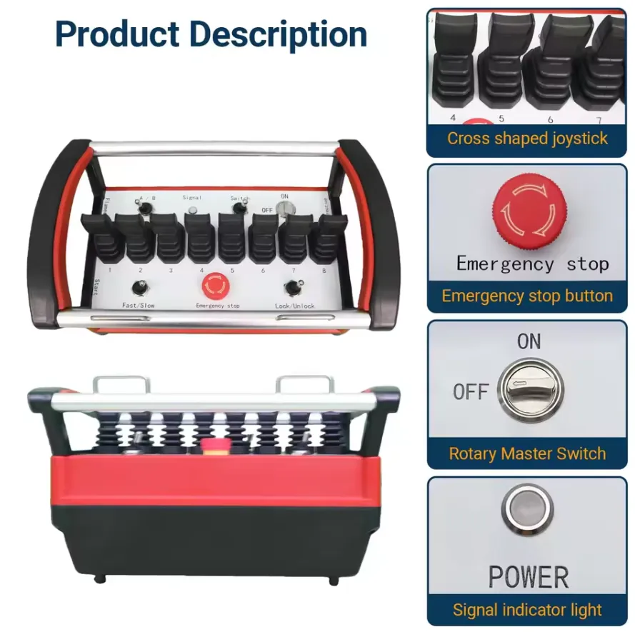
Au-delà de l'indice de protection IP, les télécommandes industrielles à usage intensif se distinguent des produits standard sur cinq autres points :
Plage de températures de fonctionnement : Les télécommandes grand public standard sont généralement conçues pour fonctionner entre -10 °C et +55 °C. Les modèles industriels à usage intensif étendent cette plage de -40 °C à +85 °C, ce qui leur permet de fonctionner dans des aciéries où la chaleur rayonnante des fours fait grimper la température ambiante bien au-delà de 60 °C, ainsi que dans des entrepôts frigorifiques ou en extérieur dans les régions nordiques, où les températures hivernales descendent bien en dessous de la limite inférieure de la plage de fonctionnement des modèles grand public.
Résistance aux vibrations et aux chocs : Les grues industrielles, notamment dans les secteurs de la sidérurgie, de l'exploitation minière et de la manutention portuaire, génèrent des vibrations structurelles continues dues aux chocs des crochets, aux oscillations des charges et au déplacement des ponts sur des joints de rails imparfaits. Les télécommandes à usage intensif sont testées conformément aux normes CEI 60068-2-6 (vibrations sinusoïdales) et CEI 60068-2-27 (chocs mécaniques) à des niveaux reflétant les conditions réelles d'exploitation, et non les valeurs minimales en laboratoire.
Résistance aux chutes : Un émetteur de télécommande utilisé dans un environnement de production tombe par terre. À plusieurs reprises. Les appareils industriels à usage intensif sont conçus pour résister à une chute de 1,5 à 2,0 mètres sur du béton sans subir de défaillance fonctionnelle, grâce à des coques en polycarbonate renforcé de fibre de verre, des surmoulages en caoutchouc absorbant l'énergie et des systèmes de fixation des composants internes qui isolent les cartes électroniques des forces d'impact.
Catégorie « Sécurité électrique » : Les systèmes à usage intensif visent au minimum le niveau de performance PLd (catégorie 3 selon la norme ISO 13849-1), avec des architectures à relais de sécurité à double canal dans le récepteur, des circuits d'arrêt d'urgence surveillés et des analyses de risques documentées. Les télécommandes commerciales standard dépassent rarement les niveaux PLb ou PLc.
Durée de vie du clavier : Les claviers à membrane industriels sont conçus pour supporter entre 2 et 5 millions de cycles d'actionnement par touche. Dans un environnement de production à cadence élevée, où un grutier effectue 50 levages par équipe et appuie plusieurs fois sur chaque touche à chaque levage, atteindre les 2 millions de cycles par touche correspond à environ 3 à 4 ans de durée de vie utile avant la première défaillance d'une touche.
Nous avons évalué les conséquences de l'utilisation d'une télécommande de qualité inférieure dans une application de grue en production. Dans un cas étudié, un site avait installé une télécommande commerciale de classe IP54 sur un pont roulant de fonderie. L'appareil est tombé en panne à cause d'une infiltration d'humidité au bout de 11 mois. Le coût de remplacement, incluant l'indisponibilité du pont roulant pendant l'installation, a représenté quatre fois la différence de prix entre l'appareil IP54 et son équivalent IP67. C'est cette réalité économique qui fait de la spécification IP67 le seul choix justifiable pour les environnements de production en continu.
En quoi la configuration des 6 à 12 touches détermine-t-elle les capacités fonctionnelles des grues, des palans et des treuils ?
Comprendre le « key count » en tant que choix d'architecture fonctionnelle
Le nombre de touches d'une télécommande industrielle sans fil pour grue n'est pas une simple caractéristique esthétique : il détermine directement les fonctions de la grue que l'opérateur peut commander, ainsi que le nombre de niveaux de vitesse disponibles. Chaque décision d'achat concernant le nombre de touches est également une décision qui porte sur les capacités opérationnelles, les besoins en formation des opérateurs et l'adéquation à l'application.
Tableau de référence des configurations de clés standard
| Nombre de touches | Fonctions de contrôle couvertes | Épreuves de vitesse | Application type | Type de grue minimum |
|---|---|---|---|---|
| 6 touches | 3 axes, vitesse unique + arrêt d'urgence | 1 vitesse par axe | Stockage, entretien, utilisation simple | Monorail aérien à poutre unique |
| 8 touches | 3 axes, vitesse unique + klaxon + 1 entrée AUX + arrêt d'urgence | 1 vitesse par axe | Fabrication générale, utilisation modérée | Poutre simple ou double |
| Clavier à 10 touches | 3 axes, deux vitesses + klaxon + arrêt d'urgence | 2 vitesses par axe | Fabrication de précision, construction métallique | Pont aérien à double poutre |
| 12 touches | 3 axes, deux vitesses + 2 AUX + klaxon + arrêt d'urgence | 2 vitesses par axe | Fonderie, manutention des matrices, ateliers de presse | Grue spéciale à double poutre |
| 14 touches | 3 axes, deux vitesses + 3 AUX + klaxon + arrêt d'urgence | 2 vitesses par axe | Grues à accessoires multifonctions | Portique en portique, monté sur rail |
| 16 touches+ | Multifonction complet + multi-palans | Au moins 2 vitesses par axe | Construction navale, ports, hydroélectricité | Très grandes grues spécialisées |
L'importance opérationnelle de la régulation à deux vitesses
Le passage d'une configuration à vitesse unique à 6 ou 8 touches à une configuration à deux vitesses à 10 ou 12 touches constitue le choix technique le plus important sur le plan opérationnel dans le processus de sélection du nombre de touches. La commande à deux vitesses offre les avantages suivants :
Vitesse de déplacement lent pour un positionnement de précision : À vitesse de rampe (généralement comprise entre 10 et 251 TP3T de la vitesse maximale), l'opérateur peut déplacer progressivement une charge suspendue vers sa position finale avec une précision bien supérieure à celle obtenue à pleine vitesse. Dans les opérations de manutention de matrices, où une matrice de 15 tonnes doit se positionner avec précision sur les goupilles de repérage du banc de presse avec une tolérance de ±2 mm, le contrôle de la vitesse de rampage n’est pas un luxe, mais une exigence technique.
À toute vitesse pour des transports en commun efficaces : Entre les points de prise en charge et de dépose, l'opérateur peut rouler à pleine vitesse, tout en respectant le temps de cycle de production atteint par les grues à une seule vitesse. La commande à deux vitesses offre à la fois l'efficacité d'un déplacement à pleine vitesse et la précision d'un positionnement à vitesse réduite.
Réduction des oscillations de la charge à l'arrêt : Le démarrage et l'arrêt d'une charge suspendue à pleine vitesse génèrent un mouvement pendulaire qui met un certain temps à s'amortir avant que la mise en place puisse avoir lieu. Le démarrage et l'arrêt à vitesse d'approche réduisent considérablement l'amplitude initiale du balancement, ce qui raccourcit la durée totale du cycle pour les tâches de précision, même si la vitesse d'approche est plus faible.
Fonctions des touches auxiliaires : ce que contrôlent réellement les boutons AUX
Sur les configurations à 12 touches et plus, les boutons auxiliaires (AUX) sont des canaux de sortie programmables pouvant être affectés à n'importe quelle fonction secondaire de la grue :
| Affectation des fonctions auxiliaires | Domaines d'application |
|---|---|
| Deuxième mouvement de levage (montée/descente) | Ponts roulants à double palan, grues de quai |
| Commande du crochet rotatif | Installation de composants de turbine, manutention de bobines |
| Réglage de la largeur de la barre d'écartement | Manutention de conteneurs, levage d'éléments préfabriqués en béton |
| Activation/désactivation de l'aimant de levage motorisé | Dépôt de ferraille, aciérie, manutention de tôles |
| Activation/désactivation du système de levage par aspiration | Manutention du verre, des panneaux et des composants de précision |
| Ouverture/fermeture du godet à grappin motorisé | Manutention de matériaux en vrac, céréales, granulats |
| Verrouillage/déverrouillage de l'attache rapide | Grues pour pelles mécaniques |
| Contournement de la limite de fin de course (à faible vitesse uniquement) | Positionnement de maintenance au-delà des limites normales |
La flexibilité dans l'attribution des fonctions auxiliaires est ce qui distingue les systèmes de niveau professionnel. Les appareils haut de gamme permettent aux techniciens de terrain de réattribuer les fonctions auxiliaires via une interface logicielle de configuration, sans avoir à modifier le câblage interne du récepteur — une fonctionnalité essentielle dans les installations où les équipements de grue sont changés de manière saisonnière ou d'un cycle de production à l'autre.
Que contient un système de télécommande sans fil IP67 à usage intensif et comment est-il conçu ?
Architecture interne de l'émetteur
L'émetteur est le composant qui est confronté aux conditions physiques les plus difficiles tout en devant garantir des performances électroniques de haute précision. Sa conception interne tient compte de ces exigences contradictoires :
Structure du logement : Une coque moulée par injection en deux parties, en polycarbonate renforcé de fibre de verre (GF-PC), offrant une résistance aux chocs environ 30% supérieure à celle de l'ABS standard. Les deux moitiés du boîtier s'assemblent le long d'une ligne de joint usinée avec précision, scellée par un joint en silicone moulé et maintenue par des fixations captives en acier inoxydable. La surface extérieure est surmoulée d’une couche de caoutchouc thermoplastique (TPR) de 3 à 5 mm d’épaisseur qui absorbe l’énergie d’impact en cas de chute, offre une surface de préhension antidérapante et contribue à l’intégrité globale de l’étanchéité.
Ensemble clavier : Un clavier à membrane en polycarbonate de qualité industrielle, doté de légendes de touches en relief et de zones de touches à code couleur. La membrane recouvre un réseau de dômes montés sur un circuit imprimé et est scellée au boîtier par un joint périphérique continu en silicone. Les inscriptions des touches sont imprimées entre les couches de la membrane (impression sous la surface), ce qui les rend résistantes à l'usure causée par des milliers de cycles d'actionnement.
Unité à microcontrôleur : Un microcontrôleur (MCU) de qualité automobile ou industrielle fonctionnant sur toute la plage de températures comprise entre -40 °C et +85 °C, capable de gérer le balayage d'une matrice de boutons à une fréquence de 100 Hz ou plus, le codage des commandes, la gestion des protocoles RF, la surveillance de la batterie, le contrôle du mode veille et la logique d'arrêt d'urgence. Le microcontrôleur est soudé au circuit imprimé principal à l'aide d'une soudure sans plomb, conformément à la norme IPC-610 Classe 3 (la classe de fiabilité la plus élevée pour les assemblages électroniques).
Module émetteur-récepteur RF : Une puce radio sub-GHz intégrant l'ensemble de la chaîne de signaux RF : synthétiseur, modulateur, démodulateur et amplificateur de puissance. Dans les implémentations FHSS, cette puce exécute la séquence de saut de fréquence sous le contrôle du microcontrôleur. La puissance de sortie est généralement comprise entre 10 et 25 dBm (10 à 316 mW), dans les limites fixées par les réglementations régionales en matière de télécommunications.
Système de batterie : Quatre piles AA logées dans un compartiment étanche doté d'un volet d'accès séparé conforme à la norme IP67. Le compartiment à piles est équipé d'un mécanisme de verrouillage à enclenchement positif (et non d'un simple bouchon à vis) avec un joint torique, afin de garantir le respect de la norme IP67 même après des centaines de remplacements de piles. Certains modèles haut de gamme utilisent des batteries lithium-ion rechargeables intégrées, dotées de ports de recharge USB-C externes obturés par des bouchons en caoutchouc.
Antenne : Soit une antenne fouet sortant du boîtier par un presse-étoupe étanche, soit une antenne à piste montée sur circuit imprimé entièrement intégrée au boîtier. Les antennes fouet offrent un meilleur gain omnidirectionnel mais sont physiquement vulnérables ; les antennes intégrées sacrifient environ 2 à 3 dB de portée en échange d'une protection totale contre les dommages physiques.
Architecture interne du récepteur
| Composant du récepteur | Spécifications | Importance sur le plan technique |
|---|---|---|
| Circuit d'entrée RF | Sensibilité comprise entre -110 et -120 dBm | Détermine le niveau de signal minimal nécessaire pour garantir un fonctionnement fiable |
| Microcontrôleur principal | Microcontrôleur industriel, de -40 °C à +85 °C | Fonctionnement sur toute la plage de températures |
| Module de relais de sécurité | Contacts NF surveillés, à double canal, compatibles SIL 2 | Chaîne d'arrêt d'urgence à sécurité intégrée câblée |
| Réseau de relais de sortie | 8 A à 16 A par relais, contacts en alliage d'argent | Gère la commutation de la bobine du contacteur de la grue avec une marge transitoire |
| Alimentation électrique | Entrée universelle 24-240 V CA/CC, sortie régulée | Un seul produit couvre toutes les tensions des tableaux de commande de grue |
| Temporisateur de surveillance | Alimentation autonome, délai d'expiration réglable entre 0,3 et 2,0 secondes | Fonctionnement en mode de sécurité indépendamment du contrôleur principal |
| Affichage de l'état | LED multicolores + écran LCD en option | Informations de diagnostic sans ouvrir le boîtier |
| Antenne | Antenne fouet externe ou circuit imprimé intégré, adapté à la bande de fréquence de l'émetteur | Placé de manière à offrir une vue directe sur la zone d'exploitation |
| Bloc de raccordement | 16 à 32 bornes à vis, montables sur rail DIN | Interface de câblage propre et fonctionnelle |
| Logement | Boîtier en acier pour rail DIN ou boîtier en plastique IP65 | Protection à l'intérieur du tableau de commande de la grue |
Options de boîtiers d'attelage haute résistance
Le récepteur est généralement installé à l'intérieur du tableau électrique de la grue, qui lui assure une protection contre les intempéries. Toutefois, dans les applications où le récepteur est monté à l'extérieur (sur la face extérieure de la poutre du pont de la grue, par exemple), il est nécessaire de disposer d'un récepteur logé dans un boîtier certifié IP65 ou IP67. Les systèmes à usage intensif conçus pour les environnements exigeants offrent ces deux options :
Récepteur à montage sur panneau : Conçu pour un montage sur rail DIN à l'intérieur d'un coffret de commande de grue existant, conforme à la norme IP65+. Format compact, borniers sur toute la largeur, emplacement prévu pour une antenne externe.
Boîtier autonome pour récepteur IP67 : Boîtier autonome en métal ou en polycarbonate renforcé, équipé de presse-étoupes, de supports de fixation et contenant l'ensemble des composants électroniques du récepteur. Utilisé lorsqu'aucun panneau de montage protégé n'est disponible ou lorsque l'environnement d'installation nécessite une protection indépendante du récepteur.
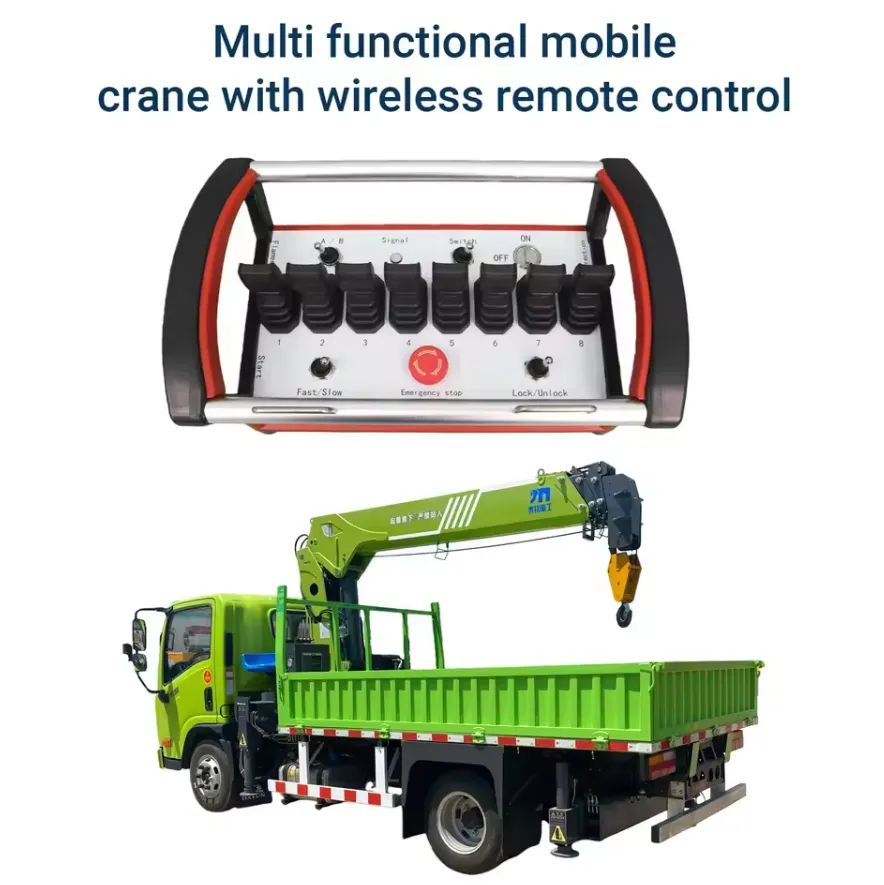
Quelle technologie de communication sans fil est utilisée dans les télécommandes de grues à usage industriel ?
Les fondements technologiques : les sciences humaines et sociales dans les environnements industriels
La technologie à spectre étalé par saut de fréquence (FHSS) n’est pas seulement une fonctionnalité privilégiée dans les télécommandes de grues industrielles à usage intensif : c’est une exigence fondamentale pour garantir un fonctionnement fiable dans les environnements RF denses caractéristiques des installations industrielles modernes. Une usine de fabrication exploitant des dizaines de points d’accès Wi-Fi, de capteurs Bluetooth, de lecteurs RFID et d’autres appareils sans fil industriels crée un environnement RF complexe dans lequel les systèmes à fréquence fixe subissent des interférences intermittentes qui se traduisent par des retards dans l’exécution des commandes ou des signaux manqués.
La technologie FHSS résout ce problème en modifiant la fréquence de fonctionnement selon une séquence pseudo-aléatoire partagée entre l'émetteur et le récepteur, avec généralement entre 50 et 200 changements de fréquence par seconde. La probabilité d’une collision prolongée entre un signal FHSS et une source d’interférence quelconque est statistiquement négligeable, même dans des environnements RF fortement encombrés. C’est pourquoi la norme ISO 23853:2021 recommande spécifiquement le FHSS ou des techniques équivalentes à spectre étalé pour les systèmes de radiocommande des grues.
Conformité aux bandes de fréquences régionales
| Région | Bandes FHSS primaires | Autorité de régulation | Certification requise |
|---|---|---|---|
| États-Unis | 902-928 MHz (bande ISM à 900 MHz) | FCC | Partie 15 de la réglementation FCC, numéro d'identification FCC requis |
| Canada | 902-928 MHz | ISED | RSS-210 |
| Union européenne | 433,05-434,79 MHz, 868,0-868,6 MHz | ETSI / Opérateurs nationaux de télécommunications | CE RED 2014/53/UE |
| Royaume-Uni | 433 MHz, 868 MHz | Ofcom | Marquage UKCA |
| Australie | 915-928 MHz | ACMA | Marque RCM |
| Japon | 426 MHz, 429 MHz | MIC | Certification TELEC |
| Chine | 433 MHz, 470-510 MHz | MIIT | Autorisation du SRRC |
| Corée du Sud | 447 MHz, 917-923,5 MHz | MSIT | Certification KC |
| Inde | 865-867 MHz | WPC | Agrément WPC |
| Brésil | 902-907,5 MHz, 915-928 MHz | Anatel | Certification Anatel |
L'utilisation d'une télécommande de grue sur une fréquence non certifiée dans l'une de ces juridictions engage la responsabilité juridique de l'exploitant de l'installation et risque de provoquer des interférences avec les infrastructures de communication critiques. Les équipes chargées des achats doivent demander le rapport d'essai de certification spécifique à chaque bande de fréquences du pays concerné, et non pas se contenter d'une simple déclaration de conformité.
Latence du signal : l'indicateur de performance opérationnelle
Le temps de réponse de bout en bout des commandes — depuis l'appui sur le bouton jusqu'à l'actionnement du contacteur du moteur — est l'indicateur de performance sans fil le plus important sur le plan opérationnel pour les applications de grues. Les systèmes industriels à usage intensif présentent le profil de latence suivant :
| Segment du chemin du signal | Durée habituelle |
|---|---|
| Détection de l'actionnement d'un bouton par le microcontrôleur de l'émetteur | 2 à 5 ms |
| Codage du microcontrôleur et préparation du module RF | 3 à 8 ms |
| Durée de transmission RF | 5 à 15 ms |
| Démodulation et décodage au niveau du récepteur | 5 à 10 ms |
| Validation de la logique de sécurité dans le microcontrôleur du récepteur | 3 à 5 ms |
| Actionnement du relais | 10 à 20 ms |
| Fermeture mécanique du contacteur de la grue | 15 à 30 ms |
| Latence totale du système (électronique) | 43 à 93 ms |
Une latence électronique totale inférieure à 100 millisecondes constitue le seuil permettant un contrôle transparent par l'opérateur : le retard est imperceptible et l'opérateur commande la grue de manière intuitive, sans avoir à compenser le décalage. Les systèmes dont la latence totale dépasse 200 millisecondes seront perçus comme lents par les grutiers expérimentés, en particulier lors du positionnement précis d’une charge qui nécessite des micro-corrections rapides.
Redondance des communications dans les applications critiques pour la sécurité
Pour les applications de grues impliquant une proximité régulière du personnel avec des charges suspendues — situation nécessitant la catégorie de sécurité PLd —, un canal de communication unique n'est pas acceptable d'un point de vue architectural. Les systèmes à usage intensif conçus pour des applications à haut risque intègrent une redondance grâce à :
Diversité à deux antennes : Deux antennes physiquement séparées sur le récepteur, dont l'électronique surveille en permanence celle qui fournit le signal le plus puissant et bascule d'une antenne à l'autre à chaque saut. Cela permet d'éliminer les zones d'ombre qui apparaissent lorsque l'orientation de l'émetteur crée un point mort dans le diagramme de rayonnement de l'antenne en direction d'une seule antenne du récepteur.
Signal de présence bidirectionnel : Le récepteur renvoie périodiquement un signal d'accusé de réception de faible puissance à l'émetteur. Si l'émetteur ne reçoit pas cet accusé de réception avant l'expiration du délai de surveillance, il interprète cette situation comme une défaillance de la liaison et l'opérateur reçoit immédiatement une alerte sonore et visuelle. Ce protocole de communication bidirectionnel réduit considérablement le risque d'une dégradation de la liaison passant inaperçue.
Dispositions relatives à la sauvegarde de Tether : Certains systèmes à usage intensif sont équipés, au niveau du récepteur, d'un connecteur permettant de brancher une télécommande de secours filaire de petite taille. Si le système sans fil présente un dysfonctionnement au cours d'une opération critique, la télécommande de secours assure la continuité immédiate de la commande sans qu'il soit nécessaire d'attendre la réparation du système sans fil.
À quelles normes de sécurité et certifications une télécommande sans fil pour grue à forte capacité doit-elle répondre ?
Le tableau complet des certifications
Les télécommandes sans fil pour grues à usage intensif, conformes à la norme IP67, doivent répondre aux exigences réglementaires dans trois domaines concomitants : la conformité des équipements radio, la sécurité des machines et les normes techniques spécifiques aux grues. Ces trois exigences doivent être satisfaites simultanément pour qu'un produit soit conforme à la législation.
Norme principale spécifique aux grues :
ISO 23853:2021 – Grues : Systèmes de commande à distance par radio est la norme internationale la plus directement applicable. Elle précise :
- Fiabilité minimale de transmission (taux d'erreur binaire inférieur à 10⁻⁶)
- Exigences relatives au délai d'expiration du circuit de surveillance (la perte du signal déclenche un arrêt de sécurité dans un délai maximal d'une seconde)
- Exigences relatives à la technologie anti-interférences (FHSS ou équivalent)
- Exigences relatives aux fonctions de sécurité (arrêt d'urgence, commande à maintien, protection contre le redémarrage)
- Protocoles d'essais environnementaux (température, humidité, vibrations, chutes, essais IP)
- Exigences en matière de marquage et de documentation.
Normes de sécurité des machines :
| Standard | Champ d'application | Pertinence pour la télécommande de grue |
|---|---|---|
| ISO 13849-1:2023 | Niveau de performance du système de commande lié à la sécurité | Détermine la force de pression (PL) requise pour les fonctions d’arrêt d’urgence et de marche par maintien |
| IEC 62061:2021 | Sécurité fonctionnelle, méthodologie SIL | Alternative à la norme ISO 13849-1 pour l'analyse de sécurité basée sur le SIL |
| EN 60204-32 | Équipement électrique des grues | Exigences en matière de commande électrique spécifiques aux grues |
| ISO 4301 | Classification des grues | La classification des groupes de charge influe sur les exigences relatives aux systèmes de contrôle |
Normes d'utilisation des grues :
| Standard | Région | Exigences clés |
|---|---|---|
| ASME B30.2 | États-Unis | Exigences relatives au système de commande des ponts roulants |
| ASME B30.16 | États-Unis | Exigences relatives à la commande des palans |
| EN 13557:2003+A2:2008 | UE | Exigences relatives au poste de commande d'une grue |
| EN 14492-2 | UE | Exigences relatives aux palans motorisés |
| Série AS 1418 | Australie | Exigences relatives aux grues et aux palans |
Exigences en matière de niveau de performance pour les applications de grues
| Application des grues | Gravité du risque | Catégorie de sécurité obligatoire | PL minimum | Nombre typique de clés à distance |
|---|---|---|---|---|
| Grue de stockage, zone inoccupée | Modéré | Catégorie 2 | PLc | 6 à 8 touches |
| Grue de chantier, personnel à proximité | Élevé | Catégorie 3 | PLd | 8 à 12 touches |
| Métal en fusion / grue à poche de coulée | Très élevé | Catégorie 3-4 | PLd-PLe | 10 à 12 touches |
| Manipulation de matières nucléaires et d'explosifs | Extrême | Catégorie 4 | PLe | 12 touches ou plus, redondantes |
| Frais généraux du chantier naval | Élevé | Catégorie 3 | PLd | 10 à 12 touches |
| Palan d'entretien, opérateur au sol | Élevé | Catégorie 3 | PLd | 6 à 10 touches |
Équipements de sécurité obligatoires sur chaque engin lourd conforme à la réglementation
Nous ne recommanderons ni ne fournirons aucune télécommande sans fil pour grue à usage intensif qui ne disposerait pas de l'une des caractéristiques suivantes, quels que soient son prix ou la notoriété de la marque :
| Fonction de sécurité | Mise en œuvre technique | Norme qui l'exige |
|---|---|---|
| Bouton d'arrêt d'urgence | Bouton à tête champignon ou bouton protégé dédié, réinitialisation manuelle requise | ISO 23853, ASME B30.2, EN 13557 |
| Commande « Hold-to-run » (commande de sécurité) | Boutons à retour par ressort ; tout mouvement s'arrête immédiatement dès qu'on les relâche | ISO 23853, OSHA 1910.179 |
| Arrêt de sécurité Watchdog | Minuterie matérielle, indépendante du microcontrôleur principal, réglable de 0,3 à 2,0 secondes | ISO 23853, EN 14492-2 |
| Protection anti-redémarrage | Une réinitialisation manuelle par l'opérateur est nécessaire après un arrêt d'urgence ou une perte de connexion | ISO 23853, ASME B30.2 |
| Identifiant unique de l'émetteur | Code de 16 bits au minimum ; 32 bits recommandés pour les sites équipés de plusieurs grues | ISO 23853 |
| Avertissement de batterie faible | Avertissement sonore et visuel avant le verrouillage en cas de mouvement | ISO 23853 |
| Verrouillage simultané des fonctions | Le matériel empêche les commandes contradictoires (par exemple, « haut » et « bas » en même temps) | EN 60204-32 |
| Circuit d'arrêt d'urgence surveillé | Relais de sécurité à deux canaux, surveillance croisée des circuits permettant de détecter le soudage des contacts | Exigence de la norme ISO 13849-1 relative au niveau de performance (PL) d |
| Boîtier anti-effraction pour émetteur | Des fixations spécialisées limitent l'accès à l'intérieur | ISO 23853 |
Comment choisir le nombre de touches et les fonctionnalités adaptés à votre application spécifique ?
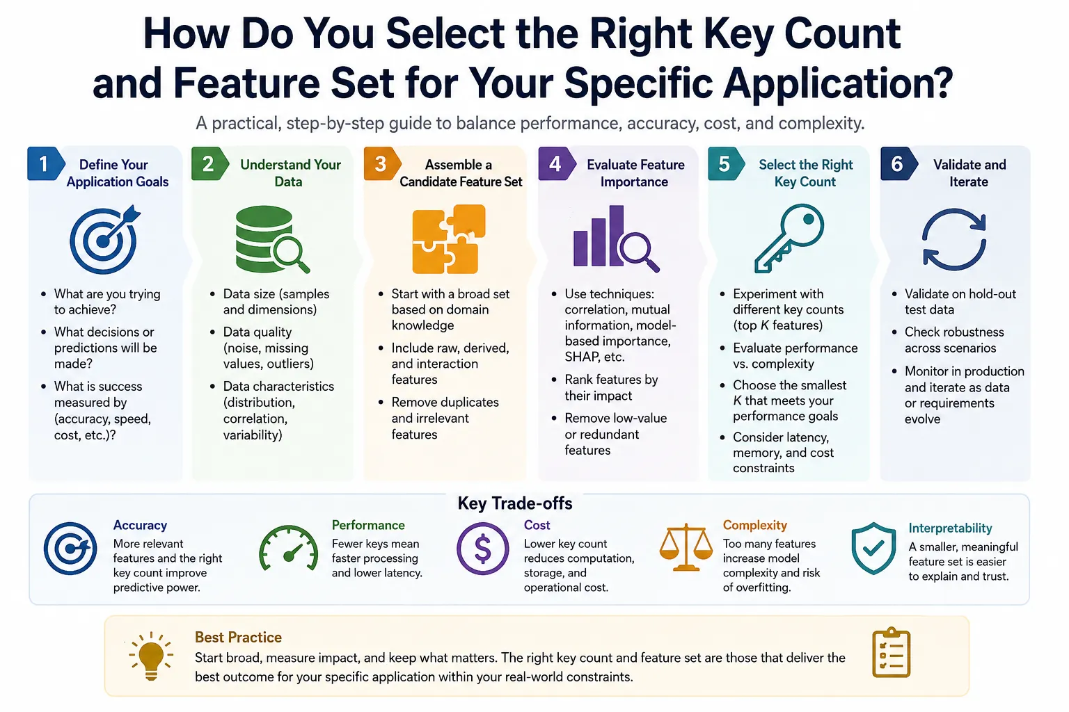
Un processus de sélection structuré en huit étapes
Étape 1 : Identifier tous les axes de mouvement de la grue
Comptez tous les mouvements indépendants que le pont roulant peut effectuer : axes de levage (un pour le levage simple, deux pour le levage double), déplacement du pont (un axe), déplacement du chariot (un axe), ainsi que toutes les fonctions supplémentaires telles que l'extension de la flèche, la rotation de la flèche secondaire ou le levage auxiliaire. Chaque sens de chaque axe nécessite un bouton ; ainsi, trois axes à vitesse unique nécessitent au minimum 6 boutons, plus l'arrêt d'urgence.
Étape 2 : Déterminer les niveaux de vitesse requis
Si l'application nécessite un positionnement précis de la charge (tolérance inférieure à ±50 mm en position finale), un système à deux vitesses est nécessaire. Si la grue est utilisée exclusivement pour des opérations répétitives à cadence élevée avec des tolérances de positionnement larges, un système à une seule vitesse peut suffire. Le système à deux vitesses double le nombre de boutons nécessaires pour les fonctions de déplacement.
Étape 3 : Énumérer les fonctions auxiliaires
Identifiez toutes les fonctions secondaires qui doivent pouvoir être commandées par l'opérateur : commande des accessoires, activation/désactivation de l'aimant ou du système d'aspiration, deuxième palan, réglage du spreader, activation de l'avertisseur sonore. Chaque fonction nécessite un bouton, et les fonctions bidirectionnelles en nécessitent deux.
Étape 4 : Calculer le nombre minimum de clés
Nombre minimum de touches = (nombre d'axes × 2 directions × niveaux de vitesse) + fonctions auxiliaires + 1 arrêt d'urgence + 1 avertisseur sonore
Exemple : grue à 3 axes et deux vitesses, avec commande de l'aimant et klaxon = (3 × 2 × 2) + 2 + 1 + 1 = 16 touches au minimum
Étape 5 : Ajouter une marge de dilatation
Ajouter une marge de 20% au nombre de touches par rapport au minimum calculé afin de permettre l'ajout futur de fonctions sans avoir à remplacer l'ensemble du système émetteur-récepteur.
Étape 6 : Vérifier la note environnementale
Choisissez l'indice de protection IP en fonction des conditions environnementales les plus défavorables sur le lieu d'installation. Reportez-vous au tableau de correspondance environnementale suivant :
| Environnement d'exploitation | Indice de protection IP minimal |
|---|---|
| Salle blanche ou bureau climatisé | IP54 |
| Fabrication générale en intérieur | IP65 |
| À l'extérieur, sous abri (quai de chargement, abri pour voiture) | IP65 |
| À l'extérieur, exposé aux intempéries, à la pluie et à la poussière | IP66 |
| Zones soumises à un lavage intensif, transformation alimentaire | IP66 |
| Marine, activités de plein air en bord de mer | IP67 |
| Fonderie, aciérie, projections importantes | IP67 |
| Zones susceptibles d'être submergées, zones inondables | IP67-IP68 |
Étape 7 : Vérifier la portée de communication
Mesurez la distance maximale entre le poste de travail de l'opérateur et la grue située à l'extrémité de sa course. Ajoutez une marge de 50%. Vérifiez que la portée nominale du système sélectionné dépasse cette valeur dans les conditions d'environnement RF prévues pour le site.
Étape 8 : Vérification du dossier de certification
Vérifiez que le système comprend : la déclaration de conformité CE ou FCC, la documentation attestant la conformité à la norme ISO 23853, l'analyse des fonctions de sécurité (calcul du niveau de performance [PL] ou du niveau d'intégrité de sécurité [SIL]), les rapports d'essais émanant de laboratoires accrédités, ainsi que le manuel d'instructions destiné aux opérateurs dans la ou les langues requises.
Matrice de décision pour le choix du nombre de clés
| Type de demande | Poids de la charge | Précision de positionnement | Nombre de touches recommandé | Indice de protection IP recommandé |
|---|---|---|---|---|
| Grue de stockage simple | Moins de 5 t | Faible (±200 mm) | 6 touches | IP65 |
| Industrie manufacturière en général | 1 à 20 t | Modéré (±100 mm) | 8 à 10 touches | IP65 |
| Fabrication métallique | 5 à 50 t | Élevé (±30 mm) | 10 à 12 touches | IP67 |
| Atelier d'emboutissage automobile | 5 à 30 t | Très élevé (±10 mm) | 12 touches | IP67 |
| Fonderie / poche de coulée | 2-200 t | Élevé (±20 mm) | 12 touches | IP67 |
| Manutention des rouleaux dans les papeteries | 5 à 50 t | Élevé (±20 mm) | 10 à 12 touches | IP66 |
| Construction navale | 50 à 5 000 t | Modéré (±50 mm) | 12 à 16 touches | IP67 |
| Manutention des conteneurs dans les ports | 20 à 100 t | Faible à modéré (±100 mm) | 12 à 16 touches | IP67 |
| Matières nucléaires | N'importe quel | Très élevé (±5 mm) | 12+ touches, PLe | IP67 |
| Maritime / offshore | 2 à 100 t | Modéré (±50 mm) | 10 à 12 touches | IP67-IP68 |
Comment installe-t-on un système de télécommande sans fil à usage intensif sur une grue, un palan ou un treuil ?
Examen technique préalable à l'installation
Avant le début de l'installation physique, un ingénieur électricien qualifié doit examiner le schéma du tableau de commande existant de la grue et vérifier les points suivants :
- Tension du circuit de commande disponible dans le tableau (24 V CA, 24 V CC, 110 V CA ou 220 V CA) pour correspondre à l'entrée d'alimentation du récepteur.
- La tension de la bobine du contacteur doit correspondre à la puissance nominale de sortie du relais du récepteur.
- Espace disponible sur le panneau et longueur du rail DIN pour le montage du récepteur.
- Parcours du câble entre le tableau électrique et l'emplacement de fixation de l'antenne.
- Si le pendentif existant doit continuer à fonctionner en parallèle avec le système sans fil.
Présentation de l'installation étape par étape
Phase 1 : Montage du récepteur et raccordement électrique
Fixez le récepteur sur un rail DIN à l'intérieur du tableau électrique principal de la grue à l'aide du matériel de fixation fourni. Raccordez l'entrée d'alimentation du récepteur à la source de tension de commande du tableau via un fusible dédié de 2 A. Raccordez le câble d'extension d'antenne entre le port d'antenne du récepteur et l'emplacement choisi pour l'antenne externe.
Le choix de l'emplacement de l'antenne est l'étape d'installation la plus souvent mal réalisée. L'antenne doit :
- En dehors de tout boîtier métallique (même les antennes partiellement protégées perdent entre 60 et 80% de leur portée nominale)
- Fixé sur la face inférieure de la poutre du pont de la grue, orienté verticalement (perpendiculairement à l'axe de la poutre du pont)
- À au moins 200 mm de toute surface métallique.
- Respectez une distance d'au moins 300 mm par rapport aux câbles d'alimentation à courant fort.
Phase 2 : Câblage des sorties vers les contacteurs de la grue
Raccordez les sorties relais du récepteur aux circuits de la bobine du contacteur du moteur de la grue, conformément au tableau d'affectation des fonctions :
| Sortie relais | En lien avec | Fonction |
|---|---|---|
| Résultat 1 | Circuit de bobine K-Hoist-Up | Levage par palan |
| Résultat 2 | Circuit de bobine K-Hoist-Down | Abaisser le palan |
| Résultat 3 | Bobine K-Bridge-East | Sens de circulation sur le pont 1 |
| Résultat 4 | Bobine K-Bridge-West | Sens de circulation sur le pont 2 |
| Résultat 5 | Bobine K-Trolley-Fwd | Sens de déplacement du chariot 1 |
| Résultat 6 | Bobine K-Trolley-Rev | Sens de déplacement du chariot 2 |
| Relais d'arrêt d'urgence (contact à ouverture) | Circuit de la bobine du relais de sécurité principal | Chaîne d'arrêt d'urgence |
Phase 3 : Intégration du circuit d'arrêt d'urgence
La sortie d'arrêt d'urgence du récepteur doit être câblée en série avec la chaîne de relais de sécurité existante de la grue — et non pas en tant que relais autonome qui ne désactive qu'une seule fonction. Cette intégration garantit que l'activation sans fil de l'arrêt d'urgence coupe simultanément l'alimentation de tous les contacteurs de mouvement de la grue, quelle que soit la fonction active à ce moment-là.
Phase 4 : Liaison émetteur-récepteur
Effectuez la procédure d'appairage en suivant les instructions du fabricant afin d'appairer l'émetteur principal et au moins un émetteur de secours au récepteur. Notez le code d'appairage unique de chaque émetteur dans le registre d'entretien.
Phase 5 : Essais de mise en service
| Test | Méthode | Critère de réussite |
|---|---|---|
| Test d'orientation de la fonction | Activez chaque fonction à l'aide de l'émetteur | Le mouvement suit le sens indiqué par le libellé du bouton |
| Temps de réponse de l'arrêt d'urgence | Activer l'arrêt d'urgence pendant la montée du palan ; mesurer le temps nécessaire à l'arrêt | Le mouvement s'arrête en moins d'une seconde |
| Test du « Watchdog » | Désactiver l'émetteur pendant le fonctionnement ; temps de réponse | Tout mouvement cesse à l'expiration du délai programmé |
| Test anti-redémarrage | Rétablir la connexion après un arrêt provoqué par le watchdog ; vérifier qu’il n’y a pas de redémarrage automatique | La machine nécessite une réinitialisation manuelle par l'opérateur |
| Test de signal sur toute la bande passante | Utiliser à la distance maximale prévue pour le fonctionnement | Toutes les fonctions fonctionnent de manière fiable |
| Test de charge | Fonctionnement à la charge nominale au crochet, toutes fonctions | Pas de cliquetis des relais, pas de dégradation du signal |
Quelle est réellement la résistance environnementale et mécanique offerte par la norme IP67 dans le cadre d'une utilisation industrielle ?
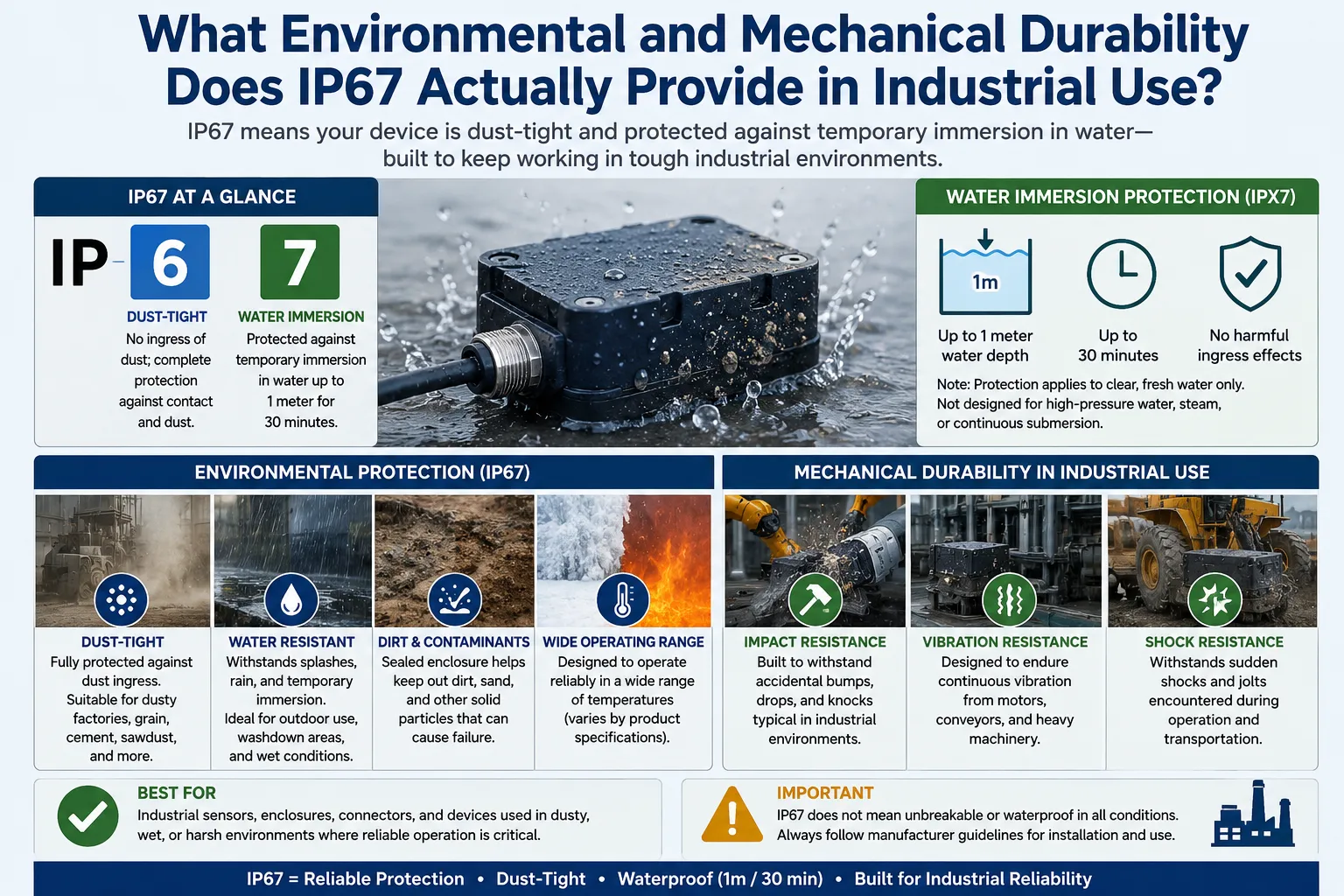
Comprendre l'indice de protection IP67 pour les applications de grues industrielles
Le système de classification IP, défini par la norme CEI 60529, utilise deux chiffres pour classer le niveau de protection contre la pénétration de particules solides et de liquides. Pour un appareil classé IP67 :
Premier chiffre “ 6 ” (Poussière) : Le boîtier est entièrement étanche à toute pénétration de poussière ou de particules solides. L'essai consiste à placer l'appareil dans une chambre à poussière contenant de la poudre de talc de 20 à 200 micromètres pendant 8 heures sous dépression ; à l'issue de cet essai, aucune poussière ne doit avoir pénétré dans le boîtier. Ce niveau de protection contre la poussière est essentiel dans les fonderies où règne la poussière métallique, les ateliers de meulage où circulent des particules abrasives, les cimenteries et les sites en extérieur exposés aux projections de sable emportées par le vent.
Deuxième chiffre “ 7 ” (Eau) : Le boîtier résiste à une immersion à une profondeur de 1 mètre pendant 30 minutes sans que l'eau ne pénètre à l'intérieur en quantité suffisante pour nuire à son fonctionnement. L'essai consiste en une immersion totale à 1 mètre de profondeur pendant exactement 30 minutes, à l'issue de laquelle aucun dysfonctionnement ne doit être constaté. Ce niveau de protection contre l'eau permet de résister à la pluie, aux projections d'eau, aux chutes accidentelles dans des flaques ou des eaux peu profondes, ainsi qu'au nettoyage de l'équipement par pulvérisation.
Ce contre quoi la norme IP67 ne protège PAS
Il est tout aussi important de comprendre les limites de l'indice de protection IP67 que de comprendre ce qu'il garantit :
| Risque | Indice de protection IP67 ? | Une note alternative est requise |
|---|---|---|
| Jet d'eau à haute pression (nettoyage au jet) | Non (testé uniquement pour l'immersion statique) | IP66 (jets à haute pression provenant de n'importe quelle direction) |
| Immersion continue de plus de 30 minutes | Non | IP68 (profondeur et durée définies) |
| Immersion profonde (plus d'un mètre) | Non | IP68 |
| Résistance chimique | Non (l'assurance IP ne couvre que les dégâts des eaux) | Essais de résistance chimique spécifiques à chaque matériau |
| Vapeur / eau à haute température | Non | Des tests spécifiques à Steam sont requis |
| Atmosphères explosives | Non | Certification ATEX ou IECEx |
| Champs électromagnétiques puissants | Non | Essais CEM (CEI 61000) |
Pour les applications nécessitant un lavage à haute pression régulier, l'indice de protection IP66 ou une combinaison IP66/IP67 est plus adapté que l'indice IP67 seul, car l'indice IP67 évalue la résistance à l'immersion, mais ne teste pas la résistance aux jets d'eau à haute pression (ce qui correspond au critère d'essai d'étanchéité de l'indice IP66).
IEC 60068 : Essais environnementaux au-delà de l'indice de protection IP
Les télécommandes industrielles à usage intensif sont soumises à des essais de qualification environnementale supplémentaires conformément à la norme CEI 60068 :
| Norme d'essai | Paramètre | Conditions d'essai types | Importance |
|---|---|---|---|
| IEC 60068-2-1 | Fonctionnement à basse température | -40 °C pendant 16 heures | Entrepôt frigorifique en plein air, dans le nord |
| IEC 60068-2-2 | Fonctionnement à chaleur sèche | +85 °C pendant 16 heures | Fonderie, près du four |
| IEC 60068-2-14 | Choc thermique | de -40 °C à +85 °C, 5 cycles | Environnements de cycles thermiques |
| IEC 60068-2-6 | Vibration sinusoïdale | 10-500 Hz, accélération de 3 g | Vibrations structurelles des grues |
| IEC 60068-2-27 | Choc mécanique | 50 g de crête, durée de 11 ms | Chutes et chocs |
| IEC 60068-2-32 | Chute libre (essai de chute) | 1,5 m sur du béton | Événements de déconnexion de l'opérateur |
| IEC 60068-2-30 | Chaleur humide, cyclique | 25-55 °C, 93% RH, 6 cycles | Environnements à forte humidité |
Résistance des matériaux des boîtiers IP67 dans des environnements chimiques
L'indice de protection IP67 régit la protection contre la pénétration d'eau, mais ne fournit aucune indication quant à la résistance du matériau du boîtier aux produits chimiques industriels. Les opérateurs travaillant dans des installations où le transmetteur est exposé à des huiles de coupe, du fluide hydraulique, des agents nettoyants caustiques ou des vapeurs acides doivent vérifier la résistance chimique spécifique du matériau du boîtier :
| Matériau du boîtier | Résistance aux huiles | Résistance aux produits caustiques | Résistance aux acides | Résistance aux UV |
|---|---|---|---|---|
| ABS | Modéré | Pauvre | Pauvre | Modéré |
| GF-PC (polycarbonate renforcé de fibres de verre) | Bien | Modéré | Modéré | Bien |
| GF-PA (polyamide renforcé de fibres de verre) | Excellent | Bien | Modéré | Bien |
| Surmoulage en TPR | Excellent | Bien | Bien | Bien |
| Quincaillerie en acier inoxydable | Excellent | Excellent | Bon (calibre 316) | Excellent |
En quoi les télécommandes sans fil industrielles à usage intensif se distinguent-elles des systèmes de commande par pendentif et par cabine ?
Comparaison objective des performances
| Caractéristique de performance | Télécommande sans fil IP67 (6 à 12 touches) | Suspension à raccordement fixe | Commande de la cabine fermée |
|---|---|---|---|
| Mobilité des opérateurs | Sans restriction (360° complets, jusqu'à 300 m) | Longueur de câble limitée (généralement entre 5 et 15 m) | Fixé à la cabine |
| Visibilité de la zone de chargement | Optimal (positions de l'opérateur au choix) | Bon (opérateur près de la charge) | Compromis (position surélevée) |
| La pluie et l'utilisation en extérieur | Excellent (indice de protection IP67) | Bon (pendentif vendu séparément) | Bon (protection de la cabine) |
| Coût d'installation | Modéré | Faible | Très élevé |
| Modernisation d'une grue existante | Oui (récepteur raccordé au tableau) | N/A (déjà présent sur la plupart des grues) | Très difficile (modification structurelle) |
| Problèmes liés à la gestion des câbles | Aucun | Importants (traînée, enchevêtrement, fatigue) | Aucun |
| Risque de trébuchement et de chute dû à un câble | Aucun | Oui (câble posé au sol ou traînant) | Aucun |
| Adéquation au cycle de service | Par intermittence à modérée | N'importe quel (sans aucune restriction en matière de connexion sans fil) | Cycle de service élevé et continu |
| Capacité maximale de la grue | Illimité (conception du système) | Généralement illimité | N'importe quelle (classification structurelle de la cabine) |
| Performances par temps froid | Excellent (appareils conçus pour des températures allant jusqu'à -40 °C) | Limité par la souplesse du câble | Cela dépend du chauffage de la cabine |
| Latence de réponse | 50 à 150 ms (électronique) | Presque zéro (connexion physique) | Presque zéro |
| Parcours de mise en conformité en matière de sécurité | ISO 23853, ISO 13849-1 | ASME B30.2, EN 13557 | ASME B30.2, EN 13557 |
| Commande de plusieurs grues à partir d'un seul poste | Possible (gestion des fréquences) | Ce n'est pas pratique | Sans objet |
| Conformité aux exigences de l'OSHA en matière de chemins de charge | Excellent (l'opérateur peut le positionner librement) | Modéré (le câble limite le positionnement) | Modéré |
Les arguments en faveur de la productivité des télécommandes sans fil IP67
Au-delà de la conformité aux normes de sécurité, les télécommandes sans fil industrielles IP67 offrent des avantages mesurables en termes de productivité qui justifient leur surcoût par rapport aux systèmes à pendentif :
Réduction du temps de repositionnement : L'opérateur utilisant une télécommande filaire doit porter physiquement celle-ci lorsqu'il se déplace entre les points de prise et de dépose de la charge. Dans les sites où des machines encombrent l'atelier de production, ce déplacement est limité par le tracé du câble. Les opérateurs utilisant une télécommande sans fil peuvent se déplacer librement jusqu'à la position optimale pour chaque phase du cycle de levage.
Fonctionnement par un seul opérateur : De nombreuses opérations de levage en hauteur nécessitant l'utilisation de commandes suspendues requièrent la présence de deux opérateurs : l'un pour actionner les commandes et l'autre pour guider la charge. Les télécommandes sans fil permettent à un seul opérateur qualifié d'assurer ces deux fonctions en se plaçant au point d'observation optimal.
Réduction du nombre d'incidents évités de justesse : Nous avons analysé les données relatives aux incidents survenus dans une usine de fabrication métallique avant et après le passage d’une commande manuelle à une télécommande sans fil sur quatre ponts roulants. Au cours des 18 mois précédant cette transition, l’usine a enregistré 7 incidents évités de justesse liés à la charge. Au cours des 18 mois qui ont suivi, ce chiffre est tombé à 1, soit une réduction de 86%. Le principal facteur contributif a été le fait que les opérateurs n'étaient plus contraints, par le câble de la télécommande pendante, de se tenir à proximité de la ligne de charge.
Quels sont les secteurs d'activité et les applications de levage qui nécessitent des télécommandes sans fil robustes conformes à la norme IP67 ?
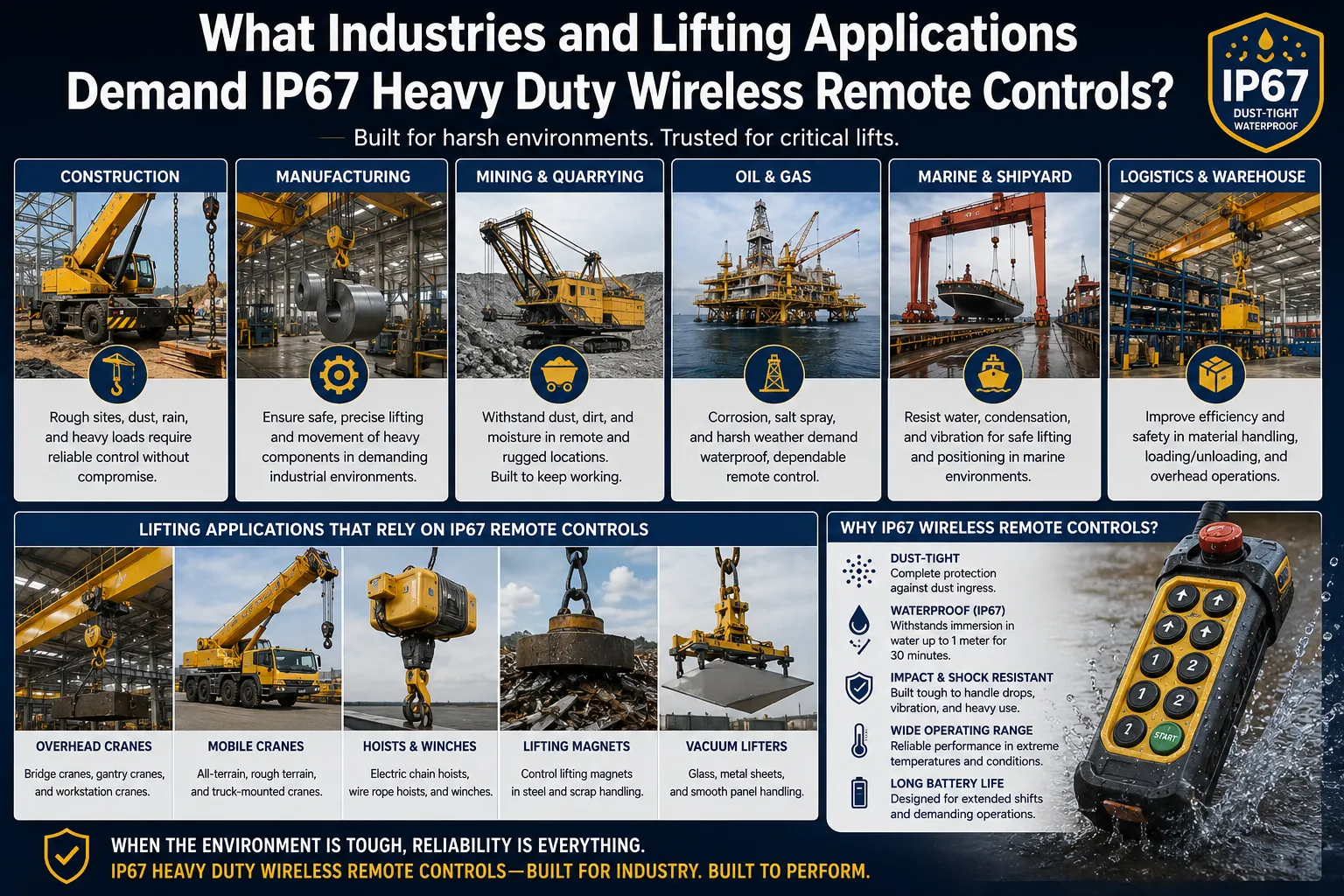
Analyse du déploiement dans le secteur
| Industrie | Type de grue/palans | Pourquoi la norme IP67 est-elle requise ? | Nombre de touches (valeur typique) | Certification supplémentaire |
|---|---|---|---|---|
| Sidérurgie | Pont roulant, grue à poche | Poussière métallique, projections d'eau dues au refroidissement | 10 à 12 touches | Rien d'autre |
| Atelier d'emboutissage automobile | Pont aérien | Copeaux métalliques, brouillard de liquide de refroidissement | 10 à 12 touches | Rien d'autre |
| Fonderie / moulage sous pression | Pont aérien | Projections de métal, températures élevées, poussière | 12 clés | Résistance aux hautes températures |
| Construction navale | Portique, pont aérien | Atmosphère marine, pluie, embruns | 12 clés | Quincaillerie de qualité marine |
| Usine de papier et de pâte à papier | Pont aérien | Projections d'eau, forte humidité | 10 à 12 touches | Rien d'autre |
| Exploitation minière à ciel ouvert | Aérien, à portique | Poussière, boue, pluie, exposition aux rayons UV | 10 à 12 touches | Rien d'autre |
| Port et conteneur | Navire-à-terre, RTG | Marine, pluie, embruns | 12 à 16 touches | Rien d'autre |
| Traitement chimique | Pont aérien | Vapeurs chimiques, lavage à grande eau | 10 à 12 touches | ATEX en zone explosive |
| Pétrole et gaz offshore | Grue de pont, sous-marine | Exposition marine totale | 12 clés | Zone ATEX 2, environnement maritime |
| Démantèlement nucléaire | Pont aérien | Contrôle de la contamination, lavage à haute pression | 12 clés | Catégorie de sécurité PLe |
| Alimentation et boissons | Aérien, monorail | Nettoyage à haute pression, à la vapeur | 10 à 12 touches | Indice de protection IP67 minimum ; qualité alimentaire |
| Fabrication aérospatiale | Dépenses générales de précision | Salle blanche, placement de précision | 12 clés | Contrôle de haute précision |
Quels sont les protocoles de maintenance qui permettent d'optimiser la durée de vie d'un système industriel à distance conforme à la norme IP67 ?
Programme d'entretien structuré
| Fréquence | Tâche de maintenance | Personne responsable | Documents requis |
|---|---|---|---|
| Avant le service (quotidien) | Tester toutes les fonctions de mouvement ; vérifier le bon fonctionnement de l'arrêt d'urgence ; vérifier l'indicateur de niveau de charge de la batterie de l'émetteur | Grutier | Registre d'inspection avant prise de service |
| Hebdomadaire | Vérifiez que le boîtier de l'émetteur ne présente pas de fissures ou de dommages au niveau des joints ; nettoyez la surface du clavier à l'aide d'un chiffon humide ; vérifiez que la lanière ou le bracelet de sécurité est en bon état | Opérateur ou technicien | Registre des inspections hebdomadaires |
| Mensuel | Vérifier que les sorties relais du récepteur s'activent correctement sous une charge légère ; inspecter le raccordement de l'antenne ; vérifier que toutes les vis des borniers du récepteur ne sont pas desserrées ; tester l'émetteur de secours | Technicien de maintenance | Registre des inspections mensuelles |
| Trimestriel | Test de signal sur toute la bande à la distance maximale de fonctionnement ; vérification du délai d'expiration du chien de garde à l'aide d'un chronomètre ; inspection de l'étanchéité du boîtier du récepteur ; nettoyage de l'antenne | Technicien de maintenance qualifié | Rapport de test trimestriel |
| Semestriel | Vérifiez que les contacts du compartiment à piles ne présentent pas de traces de corrosion ; assurez-vous que la liaison entre l'émetteur et le récepteur est intacte ; vérifiez que le micrologiciel est à jour | Technicien de maintenance de grues | Fiche d'entretien semestrielle |
| Annuelle | Contrôle fonctionnel complet conformément aux normes ASME B30.16 et OSHA 1910.179 ; essai de charge à la capacité nominale ; mesure de la résistance du circuit d'arrêt d'urgence ; vérification complète des fonctions de sécurité | Personne qualifiée (selon la définition de l'ASME) | Certificat d'inspection annuel |
| Après tout choc important | Inspection complète avant la remise en service ; test d'étanchéité IP en cas de suspicion de dommages au boîtier | Technicien de maintenance | Rapport d'inspection suite à un incident |
Protocole d'essai d'étanchéité IP67
L'étanchéité IP67 du boîtier d'un transmetteur se détériore avec le temps en raison :
- Durcissement et fissuration d'un joint en silicone sous l'effet des rayons UV.
- Les cycles thermiques qui provoquent la fatigue des matériaux des joints.
- Dommages physiques dus à des chutes et à des chocs, provoquant des fissures microscopiques dans le boîtier.
- Usure du joint du compartiment à piles due à des ouvertures répétées.
Vérifiez l'étanchéité du joint tous les trimestres en suivant cette procédure : fermez bien le couvercle du compartiment à piles. Plongez l'émetteur dans un récipient rempli d'eau propre jusqu'à une profondeur de 100 mm (et non pas jusqu'à la profondeur d'essai totale de 1 mètre). Maintenez-le immergé pendant 60 secondes. Retirez-le et vérifiez immédiatement s'il y a de l'eau à l'intérieur du boîtier en inspectant les zones transparentes, ou ouvrez le compartiment à piles et vérifiez s'il y a de l'humidité. Toute infiltration d'eau indique une défaillance du joint et nécessite le remplacement immédiat de l'émetteur ou le remplacement du joint en usine avant la prochaine utilisation.
Respect des consignes relatives aux batteries pour une production en continu
La cause la plus fréquente de perturbation opérationnelle liée aux télécommandes sans fil des grues est l'épuisement de la batterie au cours d'un service. Un protocole structuré de gestion des batteries permet d'éliminer complètement ce type de défaillance :
- Remplacer les piles des émetteurs selon un calendrier fixe (tous les 60 jours pour les grues utilisées à un rythme soutenu, tous les 90 jours pour celles utilisées moins fréquemment)
- Notez chaque date de remplacement des piles ainsi que la marque et le type de celles-ci dans le carnet d'entretien.
- Veillez à disposer d'un stock de piles neuves sur chaque poste de travail équipé d'une grue — ne retirez jamais les piles de l'émetteur d'une grue pour les utiliser sur une autre.
- Lorsqu'un avertissement de batterie faible se déclenche, terminez le levage en cours en toute sécurité et remplacez immédiatement les batteries ; ne continuez pas à utiliser l'appareil lorsque l'avertissement de batterie faible est activé.
- Pour les kits d'émetteurs rechargeables, mettez en place une procédure de recharge à la fin de chaque service et fournissez un émetteur de rechange chargé par poste de grue.
Comment la technologie des télécommandes sans fil industrielles à usage intensif va-t-elle évoluer d'ici 2026 ?
Développements technologiques en cours
Réseau 5G privé pour le contrôle d'une flotte de grues :
Plusieurs grandes usines d'assemblage automobile et aciéries ont déployé des réseaux 5G privés qui servent de backbone de communication pour toutes les télécommandes sans fil des grues présentes dans leurs installations. La 5G privée offre une latence radio inférieure à 20 ms, permet des communications cryptées entre toutes les grues au sein d’un réseau unique et géré, et donne au service informatique une visibilité sur les indicateurs de performance du système sans fil. Dans ces installations, les télécommandes sans fil des grues se connectent au réseau 5G privé plutôt que d’utiliser des liaisons RF point à point dédiées, ce qui modifie fondamentalement l’architecture réseau du contrôle des grues.
Surveillance de la charge en temps réel sur l'écran de l'émetteur :
Les télécommandes haut de gamme de la gamme Premium, modèle 2026, destinées aux applications lourdes, intègrent une communication bidirectionnelle qui transmet les données du capteur de charge, situées au niveau du bloc de crochet de la grue, vers l'écran LCD de l'émetteur. L'opérateur visualise ainsi le poids actuel de la charge en temps réel, sans avoir à consulter un indicateur de charge séparé monté sur un panneau. Cette fonctionnalité présente un intérêt pratique dans deux contextes d’utilisation : d’une part, pour vérifier que le crochet a bien saisi la charge avant de commencer le levage (l’affichage du poids passe de zéro au poids de la charge) ; d’autre part, pour surveiller la charge tout au long du levage afin de détecter une surcharge progressive due à un déplacement de la charge ou à l’ajout de matériaux supplémentaires pendant la manœuvre.
Alertes de maintenance prédictive assistées par l'IA :
Les unités de réception dotées d’une fonction d’enregistrement des données consignent le nombre de cycles, les déclenchements de l’arrêt d’urgence, les indicateurs de qualité du signal et les profils de courant d’actionnement des relais. Les algorithmes d’apprentissage automatique qui traitent ces données identifient les anomalies précurseurs de défaillances de composants — comme un relais présentant une résistance de contact croissante au fil des activations successives, signe d’une défaillance imminente des contacts — et génèrent des alertes de maintenance avant que la défaillance opérationnelle ne se produise. Plusieurs grands fabricants de systèmes de commande de grues ont intégré cette fonctionnalité dans leurs gammes de produits prévues pour 2025-2026.
Appareils robustes conformes à la norme ATEX Zone 1, dotés d'un ensemble complet de fonctionnalités :
Le marché des télécommandes de grue conformes à la norme ATEX a toujours proposé des fonctionnalités réduites par rapport aux modèles industriels standard, car les contraintes de conception liées à la sécurité intrinsèque, nécessaires pour obtenir la certification Zone 1, limitaient les options en matière de composants électroniques. Les télécommandes ATEX de deuxième génération pour usage intensif en Zone 1, désormais disponibles en 2026, offrent les mêmes configurations de 6 à 12 touches, la communication FHSS, l'indice de protection IP67 et l'architecture de sécurité PLd que leurs équivalents non ATEX, ouvrant ainsi la voie à une capacité de commande à distance entièrement sans fil pour les usines chimiques, les silos à céréales et les opérations de grues dans les raffineries.
Protocoles de communication cryptés :
À la suite d'études de sécurité démontrant que les télécommandes de grue à code fixe plus anciennes pouvaient théoriquement être piratées par des attaques par rejeu de signal, le secteur a largement adopté la communication chiffrée AES-128 ou AES-256 dans le protocole FHSS. Il s'agit désormais d'une spécification de base pour les installations de grues au sein des administrations, de l'armée et des infrastructures critiques, et elle est de plus en plus souvent exigée dans les appels d'offres du secteur privé en tant qu'exigence de sécurité standard.
Optimisation ergonomique grâce à des programmes de retour d'information des opérateurs :
Plusieurs fabricants ont mené des programmes structurés de retour d’expérience auprès des opérateurs afin de mesurer la fatigue liée à la prise en main, les angles d’accès aux touches et la position du poignet sur des périodes de travail complètes. Il en résulte une nouvelle génération d’émetteurs plus légers (moins de 380 g, piles comprises, pour les configurations à 12 touches), dotés de surfaces de préhension profilées épousant la courbure naturelle de la main, de groupes de touches à zones de couleur permettant d’identifier les fonctions au toucher sans confirmation visuelle, et d’une différenciation tactile entre les types de touches (les touches de mouvement ont un profil distinct de celui des touches auxiliaires).
Foire aux questions (FAQ)
1 : Que signifie exactement la norme IP67 sur une télécommande sans fil destinée à une grue à usage intensif, et comment est-elle testée ?
La certification IP67 d’une télécommande sans fil pour grue à usage intensif signifie que le boîtier répond à deux niveaux de protection testés indépendamment. Le chiffre “ 6 ” indique une protection totale contre la poussière : le boîtier est testé dans une chambre contenant de la poudre de talc fine pendant 8 heures sous dépression, sans qu’aucune poussière ne puisse y pénétrer. Le chiffre “ 7 ” signifie une protection contre l’immersion : l’émetteur complet est immergé à 1 mètre de profondeur dans de l’eau douce pendant 30 minutes, à l’issue desquelles il ne doit présenter aucun dysfonctionnement. Ces deux tests sont réalisés sur des échantillons représentatifs de la production, conformément aux protocoles d’essai de la norme CEI 60529. En termes d’utilisation dans les environnements de grues, l’indice IP67 signifie que le transmetteur résiste à la poussière métallique, au brouillard d’huile de coupe et aux projections d’eau typiques des aciéries et des ateliers de fabrication, et qu’il résiste à des chutes accidentelles dans des bacs de liquide de refroidissement ou des flaques d’eau. La norme IP67 n’offre pas de protection contre les jets de nettoyage à haute pression ni contre une immersion prolongée en profondeur, qui nécessitent respectivement les indices de protection IP66 et IP68.
2 : Combien de touches faut-il sur une télécommande sans fil pour un pont roulant standard ?
Un pont roulant standard à trois axes équipé d'un seul palan nécessite au moins 7 commandes fonctionnelles : montée du palan, descente du palan, déplacement du pont vers l'est, déplacement du pont vers l'ouest, avance du chariot, recul du chariot, ainsi qu'un avertisseur sonore. L'ajout d'un bouton d'arrêt d'urgence (obligatoire) porte le total à 8. Cela correspond à une configuration standard d'émetteur à 8 touches. Si une commande à deux vitesses est requise pour l’axe de levage, deux boutons supplémentaires sont nécessaires (levage lent et levage rapide, ou un seul bouton « haute vitesse » qui active la vitesse maximale lorsqu’on appuie dessus alors que le bouton standard est déjà actif), ce qui porte le minimum à un émetteur à 10 touches. Pour les ponts à double palan ou les ponts équipés d’une commande d’accessoires (aimant, ventouse, crochet rotatif), ajoutez 2 touches par fonction bidirectionnelle supplémentaire. La plupart des responsables des achats spécifient un nombre de touches supérieur d’un cran au minimum calculé afin de disposer d’une capacité d’extension sans avoir à remplacer l’ensemble du système.
3 : Quelle est la portée de fonctionnement d'une télécommande sans fil IP67 pour grue à usage intensif dans une aciérie ?
Dans un atelier typique d’aciérie doté d’une structure métallique, de ponts roulants sur les deux voies de circulation et de nombreux autres appareils sans fil fonctionnant simultanément, une télécommande sans fil FHSS haute performance pour ponts roulants, d’une portée nominale de 300 mètres en plein air, offrira généralement une portée de fonctionnement fiable comprise entre 50 et 150 mètres. Les principaux facteurs d’atténuation sont la structure métallique du pont de la grue elle-même (qui peut bloquer ou réfléchir le trajet des ondes radio entre l’opérateur et l’antenne réceptrice montée sur le pont), les poteaux métalliques et la charpente du bâtiment, ainsi que les interférences provenant d’autres équipements sans fil. Le moyen le plus efficace de maximiser la portée de fonctionnement dans une aciérie consiste à positionner soigneusement l’antenne : il faut monter l’antenne externe du récepteur sur la face inférieure de la poutre du pont de la grue, orientée verticalement, à un endroit offrant une ligne de visée vers les positions de travail prévues de l’opérateur sur toute la course de la grue. Grâce à un placement optimal de l’antenne, les systèmes FHSS utilisés dans les aciéries atteignent régulièrement une portée fiable de 80 à 120 mètres.
4 : Un seul émetteur sans fil peut-il commander plusieurs grues dans la même baie ?
Un seul émetteur sans fil peut être appairé à plusieurs récepteurs (chacun installé sur une grue différente), à condition que le système intègre une fonction de sélection de grue. Certains systèmes à grues multiples utilisent une séquence de boutons de sélection dédiée qui active le récepteur d’une grue spécifique tout en suspendant simultanément les réponses de tous les autres récepteurs appairés. D'autres configurations utilisent des émetteurs distincts pour chaque grue, ce qui est plus simple du point de vue de la sécurité car cela élimine le risque d'activer la mauvaise grue à la suite d'une séquence de sélection erronée. Pour les applications où un opérateur gère plusieurs grues depuis un poste central — ce qui est courant dans les entrepôts automatisés et certaines installations industrielles —, les systèmes de commande multi-grues dotés de sélecteurs physiques sur la console de l'émetteur constituent la solution appropriée. Ces systèmes intègrent des verrouillages qui empêchent plusieurs grues de répondre simultanément aux commandes de mouvement.
5 : Que dois-je vérifier pour m'assurer qu'une télécommande sans fil pour grue est conforme aux exigences de la norme ISO 23853 ?
Pour confirmer la conformité à la norme ISO 23853:2021, il ne suffit pas de se contenter de la déclaration d’un fournisseur. Demandez les documents spécifiques suivants : le rapport d’essai du produit émanant d’un laboratoire d’essais accrédité, confirmant la conformité aux exigences des clauses de la norme ISO 23853, y compris les résultats de mesure du taux d’erreurs sur les bits, les comptes rendus des essais de vérification du délai d’expiration du chien de garde et les certificats d’essais IP. Demandez le document d’analyse des fonctions de sécurité présentant le calcul du niveau de performance pour la fonction d’arrêt d’urgence et la fonction « hold-to-run » (maintien pour fonctionnement) selon la méthodologie de la norme ISO 13849-1 (y compris les paramètres MTTF, DC et CCF pour l’architecture de relais de sécurité à double canal). Demandez la déclaration de conformité mentionnant expressément la norme ISO 23853:2021 parmi les normes appliquées. Un fournisseur incapable de fournir l’un de ces documents avance une allégation de conformité non fondée. Pour les applications critiques (exigences PLd/PLe), faites examiner la documentation par un ingénieur indépendant spécialisé en sécurité fonctionnelle avant d’accepter la livraison.
6 : Comment la température influe-t-elle sur les performances d'une télécommande sans fil IP67 dans une fonderie ?
Les environnements de fonderie posent deux défis thermiques simultanés : les températures ambiantes à proximité des points d’accès aux fours peuvent atteindre 70 à 90 °C, et les variations de température entre les zones des fours et les parties plus fraîches de l’usine créent des chocs thermiques qui sollicitent les joints d’étanchéité des boîtiers et les soudures des composants. Une télécommande sans fil IP67 à usage intensif destinée aux fonderies doit être spécifiquement homologuée pour une température de fonctionnement maximale de +85 °C, et non simplement de +55 °C (la norme pour les appareils grand public). À des températures supérieures à +55 °C, les piles alcalines standard subissent une autodécharge accélérée et peuvent gonfler, compromettant ainsi l’étanchéité du compartiment à piles. Les piles primaires au lithium (conçues pour résister à +85 °C) constituent le choix privilégié pour les émetteurs utilisés en fonderie. L’écran LCD de l’émetteur (le cas échéant) doit être équipé d’un module d’affichage adapté aux hautes températures, car la technologie LCD standard devient lente au-delà de +60 °C et cesse de fonctionner au-delà de +70 °C. Pour un fonctionnement prolongé à moins de 5 mètres de l’accès au four ouvert, il est recommandé de protéger thermiquement le câble d’antenne du récepteur afin d’éviter la dégradation du diélectrique du câble coaxial.
7 : Quelle est la bonne façon de stocker et de transporter une télécommande sans fil IP67 à usage intensif entre deux services ?
Lorsque l'émetteur n'est pas utilisé, rangez-le dans un emplacement prévu à cet effet, à l'écart de la zone de chargement de la grue : ne le laissez jamais sur le pont de la grue, où il pourrait être heurté par des accessoires de levage, et ne le suspendez jamais au crochet ou à un câble. La lanière de l’émetteur doit être fixée à un support fixe ou à un étui situé près du poste de commande de la grue, de manière à ce qu’il reste accessible tout en étant protégé. Avant de le ranger, vérifiez que le bouton d’arrêt d’urgence a été activé et que l’émetteur est hors tension (en mode veille ou avec la batterie retirée en cas de stockage prolongé). Dans les installations équipées de plusieurs grues, étiquetez chaque émetteur avec la désignation de la grue à laquelle il est associé à l’aide d’un marquage indélébile afin d’éviter que les opérateurs n’utilisent le mauvais émetteur sur la mauvaise grue. Lors d’un transport entre sites ou pour une intervention technique, rangez l’émetteur dans son emballage d’origine ou dans un étui spécialement conçu et doublé de mousse. Ne stockez jamais les émetteurs avec des piles installées pendant plus de 3 mois, car les fuites des piles alcalines peuvent contaminer et endommager les contacts internes.
8 : Peut-on utiliser une télécommande sans fil à usage intensif sur un palan installé dans une zone électrique classée ?
Les télécommandes sans fil standard IP67 pour grues à usage intensif ne sont pas adaptées à une utilisation dans des zones classées comme dangereuses (atmosphères explosives) selon les normes ATEX, l'article 500 du NEC ou les normes IECEx. Ces zones nécessitent des équipements spécialement conçus et certifiés pour empêcher l'inflammation de l'atmosphère environnante. Des télécommandes sans fil pour grues à usage intensif certifiées ATEX sont disponibles dans le commerce pour les zones classées Zone 1 (présence de gaz en fonctionnement normal) et Zone 2 (présence de gaz uniquement dans des conditions anormales) ; elles portent le marquage « Ex » accompagné des désignations appropriées relatives au groupe d’appareils, à la catégorie et à la classe de température. À partir de 2026, plusieurs fabricants proposeront des télécommandes sans fil robustes conformes à la zone 1 de la directive ATEX, offrant les mêmes capacités fonctionnelles que les modèles industriels standard (6 à 12 touches, FHSS, IP67, niveau de sécurité PLd). Vérifiez toujours que le marquage ATEX spécifique correspond bien à la classification de la zone dangereuse de votre installation avant de déployer un système de télécommande dans une zone classée.
Pour empêcher toute utilisation non autorisée d’une télécommande sans fil de grue, il est nécessaire de mettre en place un contrôle d’accès à plusieurs niveaux. Contrôle d’accès physique : rangez l’émetteur dans une armoire verrouillée lorsqu’il n’est pas utilisé, en appliquant les mêmes pratiques de gestion des clés que celles utilisées pour la clé de la cabine de la grue. Contrôle d’accès électronique : certains récepteurs avancés exigent la saisie d’un code PIN avant de répondre à toute commande de l’émetteur, à l’instar d’une serrure à clavier. L’opérateur saisit un code de 4 à 6 chiffres sur le clavier de l’émetteur (s’il dispose de touches numériques) ou sur un clavier séparé monté sur le tableau de commande de la grue avant que le récepteur n’accepte les commandes de mouvement. Contrôle opérationnel : mettez en place une procédure officielle de passation de service entre les équipes, dans le cadre de laquelle l’opérateur sortant remet physiquement l’émetteur à l’opérateur entrant et l’informe de tout problème opérationnel, les deux signant le registre de la grue. Pour les applications à haute sécurité telles que les installations nucléaires ou les usines chimiques, l’activation biométrique de l’émetteur (capteur d’empreintes digitales intégré au boîtier de l’émetteur) est disponible dans le commerce auprès de fournisseurs spécialisés.
10 : Quelle est la durée de vie typique d'une télécommande sans fil pour grue industrielle à usage intensif de classe IP67 ?
Une télécommande sans fil industrielle de type grue, de classe IP67 et à usage intensif, utilisée dans des conditions de production normales, a une durée de vie typique de 5 à 10 ans avant que les effets cumulés de l’exposition à l’environnement, de l’usure due à l’actionnement des touches et du vieillissement des composants électroniques ne justifient son remplacement. Les facteurs limitants sont les suivants : l'usure du clavier (les claviers à membrane industriels ont une durée de vie nominale de 2 à 5 millions de cycles ; à raison de 100 actionnements par équipe sur une année de 250 équipes, la limite de 2 millions de cycles correspond à environ 8 ans), la dégradation des joints du boîtier due aux rayons UV, aux produits chimiques et à la chaleur (qui se manifeste généralement par un durcissement du joint ou une fissuration de la surface du boîtier au bout de 5 à 8 ans), ainsi que l’obsolescence éventuelle des composants électroniques, rendant la réparation non rentable. Le récepteur a généralement une durée de vie supérieure de 30 à 50% à celle de l’émetteur, car il fonctionne dans l’environnement protégé du panneau. Le remplacement est indiqué lorsque les coûts de réparation dépassent 50% du prix d’un appareil neuf, que les pièces de rechange ne sont plus disponibles, que l’appareil ne répond plus aux normes de sécurité en vigueur ou que la fréquence des pannes sur site dépasse une par mois malgré la maintenance. Le fait de disposer d’un émetteur de rechange pré-appairé par grue permet d’éviter toute interruption de production lorsque l’appareil principal arrive en fin de vie.
Sources et références vérifiables
Les données techniques, les exigences de sécurité, les normes environnementales et les références réglementaires mentionnées tout au long de cet article sont tirées des sources primaires faisant autorité suivantes :
- ISO 23853:2021 – Grues : Systèmes de commande à distance par radio (Organisation internationale de normalisation) – Norme internationale de référence en matière de conception, de sécurité et de performances des systèmes de commande à distance sans fil pour grues et palans.
- IEC 60529:2013 – Degrés de protection assurés par les enveloppes (code IP) (Commission électrotechnique internationale) – Norme définissant les méthodes d'essai et le système de classification de l'indice de protection IP.
- ISO 13849-1:2023 – Sécurité des machines : éléments des systèmes de commande liés à la sécurité (Organisation internationale de normalisation) – Cadre d'évaluation du niveau de performance des fonctions de sécurité des systèmes de commande des grues.
- IEC 62061:2021 – Sécurité des machines : Sécurité fonctionnelle des systèmes de commande électriques liés à la sécurité (Commission électrotechnique internationale) – Méthode alternative d'analyse de la sécurité fondée sur le SIL.
- ASME B30.2-2022 – Ponts roulants et portiques (American Society of Mechanical Engineers) – Norme américaine relative aux exigences en matière de conception, d'inspection et de commande des ponts roulants.
- ASME B30.16-2022 – Palans aériens suspendus et fixes (American Society of Mechanical Engineers) – Norme américaine relative aux exigences applicables aux systèmes de commande des palans.
- EN 13557:2003+A2:2008 – Grues : Commandes et postes de commande (Comité européen de normalisation) – Norme européenne relative à la conception des systèmes de commande des grues, y compris les systèmes sans fil.
- EN 14492-2:2006+A1:2009 – Ponts roulants : palans à entraînement motorisé (Comité européen de normalisation) – Norme européenne relative aux exigences de conception et de commande des palans motorisés.
- Directive européenne 2014/53/UE relative aux équipements radioélectriques (RED) (Parlement européen et Conseil) – Cadre juridique régissant le marquage « CE » des équipements de transmission sans fil sur les marchés de l'Union européenne.
- Directive européenne 2006/42/CE relative aux machines (Parlement européen et Conseil) – Exigences essentielles de santé et de sécurité applicables aux machines, y compris les systèmes de commande des grues.
- FCC, partie 15 – Appareils fonctionnant en radiofréquences (Commission fédérale des communications des États-Unis) – Exigences réglementaires américaines relatives aux appareils sans fil industriels ne nécessitant pas de licence.
- ETSI EN 300 220-2 V3.2.1 (Institut européen des normes de télécommunications) – Norme technique relative aux appareils sans fil à courte portée fonctionnant dans les bandes ISM de l'UE.
- IEC 60068-2-6 – Essais environnementaux : vibrations sinusoïdales (Commission électrotechnique internationale) – Norme relative aux essais de vibration pour l'évaluation de la durabilité des équipements électroniques.
- IEC 60068-2-27 – Essais environnementaux : Chocs (Commission électrotechnique internationale) – Norme relative aux essais de résistance aux chocs mécaniques pour la qualification des équipements électroniques.
- Directive ATEX 2014/34/UE (Parlement européen et Conseil) – Cadre juridique régissant les équipements destinés à être utilisés dans des atmosphères explosives, applicable aux télécommandes sans fil pour grues certifiées ATEX.
- OSHA 29 CFR 1910.179 – Ponts roulants et portiques (Administration américaine de la sécurité et de la santé au travail) – Réglementation américaine relative à la sécurité des grues dans l'industrie générale, couvrant les exigences en matière de systèmes de commande.
Configurez votre système de télécommande sans fil IP67 à usage intensif avec Nomi
Chez Nomi, notre équipe d'ingénieurs travaille en étroite collaboration avec les intégrateurs de systèmes de grues, les ingénieurs en sécurité des installations et les responsables des achats afin d'adapter précisément la configuration de la télécommande sans fil robuste IP67 (6 à 12 touches) aux exigences fonctionnelles de chaque application, aux conditions environnementales et aux obligations réglementaires.
Notre gamme industrielle à usage intensif comprend aussi bien des systèmes à 6 touches conformes à la norme IP67 destinés aux applications standard de ponts roulants que des unités professionnelles FHSS à 12 touches dotées de sorties analogiques compatibles avec les variateurs de fréquence (VFD), d'un affichage bidirectionnel de la charge et d'une documentation complète en matière de sécurité conforme aux normes CE, FCC et ISO 23853. Chaque système est livré avec un émetteur de rechange pré-appairé, une documentation complète sur le câblage et une garantie de deux ans sur tous les composants.
Contactez dès aujourd'hui notre équipe technico-commerciale pour bénéficier d'une analyse gratuite du cahier des charges de votre application. Indiquez-nous le type de grue, l'environnement de travail, les principales exigences fonctionnelles et le pays de destination, et nous vous proposerons, dans un délai de trois jours ouvrés, une recommandation détaillée concernant le système, accompagnée de la documentation de certification.
Demander une fiche technique ou contactez un spécialiste Nomi en commande de grues afin de valider les spécifications de votre télécommande sans fil IP67 pour usage intensif avant d'engager votre budget d'achat.