

Télécommande hydraulique
Produits
PRODUITS
NOUS CONTACTER
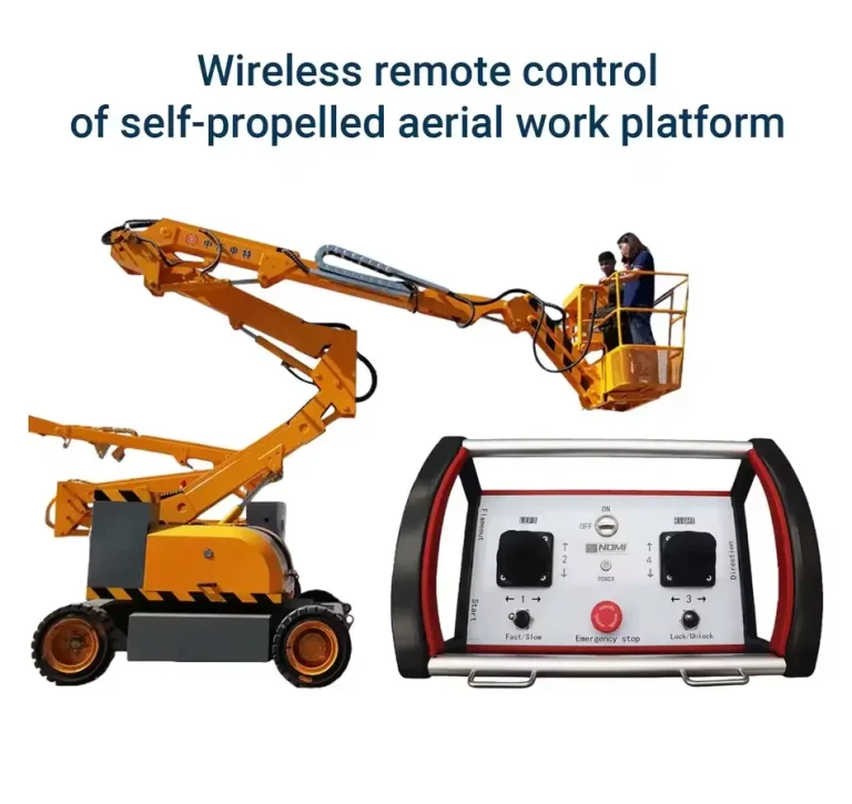

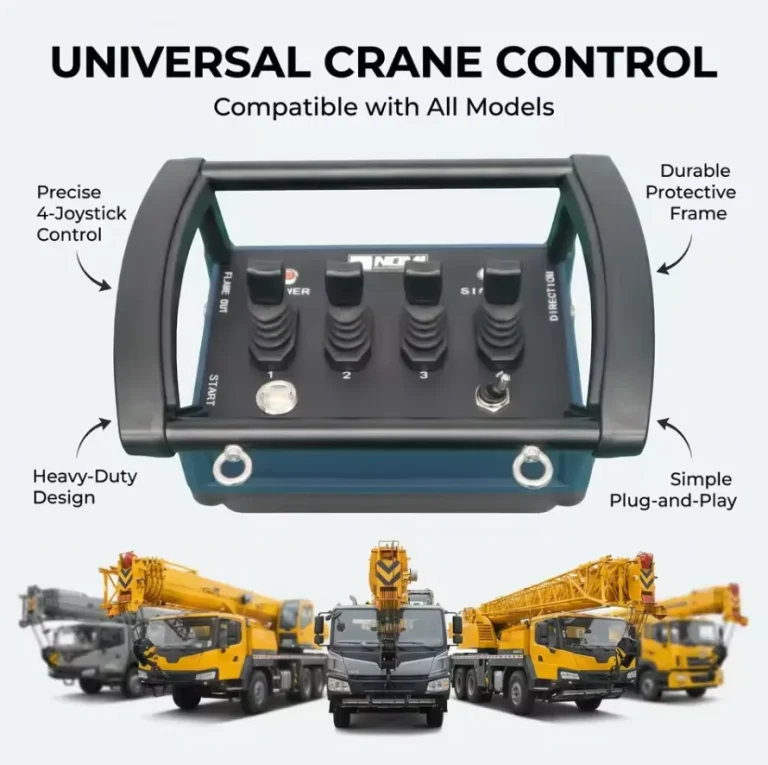
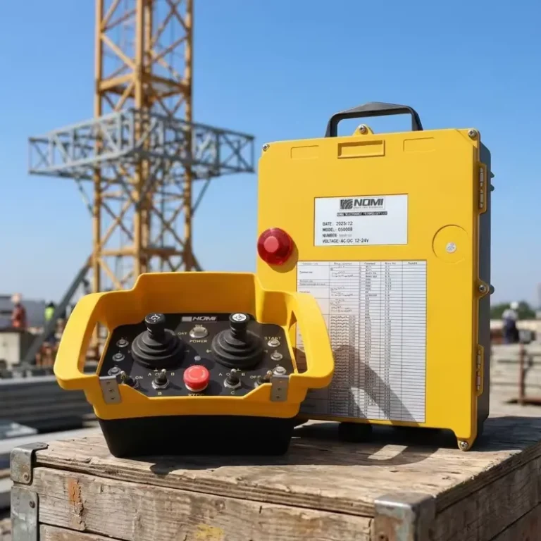
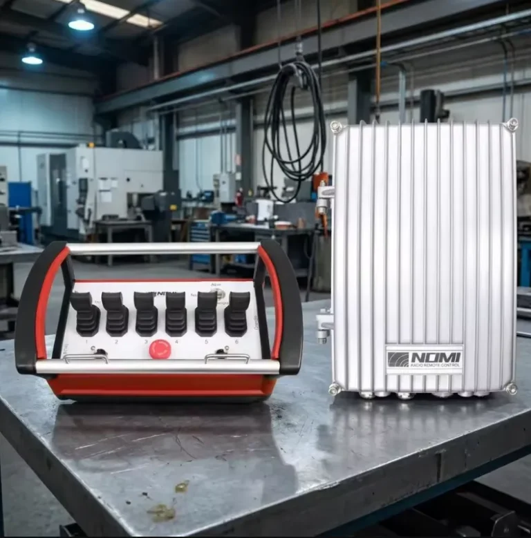
Les kits de mise à niveau sans fil pour les systèmes de commande hydraulique à distance permettent de convertir des machines hydrauliques à commande manuelle en machines radiocommandées en 4 à 16 heures, sans remplacer le circuit hydraulique existant, ce qui améliore la sécurité des opérateurs de 40% à 65% et élimine les défaillances de câblage responsables de 23% des temps d’arrêt des systèmes de commande hydrauliques. Les systèmes de modernisation, compatibles avec les distributeurs hydrauliques proportionnels et tout ou rien, fonctionnent à 868 MHz ou 915 MHz en mode FHSS (modulation à saut de fréquence) et intègrent des architectures de sécurité certifiées SIL 2. Chez Nomi, nous avons conçu et déployé ces conversions à l'échelle mondiale dans les secteurs de l'exploitation forestière, de la construction, de la marine et des presses industrielles.
Qu'est-ce qu'un système de commande à distance hydraulique et comment fonctionnent les kits de mise à niveau sans fil ?
Un système de commande hydraulique à distance est une architecture de commande qui remplace l'actionnement mécanique direct ou manuel des distributeurs hydrauliques par des électrovannes ou des actionneurs proportionnels à commande électrique, pilotés soit par des commandes suspendues câblées, soit, dans le cadre d'applications de modernisation sans fil, par des signaux radioélectriques émis depuis un émetteur portatif ou porté sur le corps par l'opérateur.
Les kits de mise à niveau sans fil permettent d’ajouter une fonctionnalité de commande radio aux machines hydrauliques existantes sans avoir à modifier le circuit hydraulique. Cette mise à niveau consiste à installer des actionneurs de vanne à commande électrique sur les tiroirs des vannes de commande directionnelles existantes, à raccorder un récepteur au système électrique de la machine et à fournir à l’opérateur un émetteur radio portable. Du point de vue du système hydraulique, la vanne reçoit les mêmes commandes de déplacement du tiroir que celles qu’elle recevrait d’un levier mécanique ; la différence réside dans le fait que la force qui déplace le tiroir provient d’un solénoïde électrique commandé par radio plutôt que de la main de l’opérateur.
Cette approche de modernisation permet de conserver la pompe hydraulique existante, les soupapes de sécurité, les ensembles de filtration, les actionneurs et la topologie du circuit. Le coût d’investissement est nettement inférieur à celui du remplacement du système hydraulique, et le temps d’arrêt lié à l’installation se mesure en heures plutôt qu’en jours ou en semaines. Selon le rapport «Mobile Hydraulics Market Intelligence Report» publié par Moog Industrial (2022), plus de 60% de mises à niveau des systèmes de commande à distance hydrauliques dans les secteurs des engins de chantier et des machines forestières sont désormais réalisées sous forme de modernisations sans fil sur des machines existantes, plutôt que par l’achat de nouveaux équipements dotés de systèmes sans fil montés en usine.
Le principe de fonctionnement d'un système de modernisation hydraulique sans fil est simple : l'opérateur actionne un joystick ou appuie sur un bouton de l'émetteur sans fil ; l'émetteur code la commande sous forme de paquet radio et la transmet à un débit de 20 à 100 paquets par seconde ; le récepteur installé sur la machine décode le paquet, vérifie le code d'adresse et la somme de contrôle CRC, puis active la sortie de l'électrovanne correspondante ; l'électroaimant déplace le tiroir de la vanne de commande directionnelle, dirigeant le débit hydraulique vers l'actionneur sélectionné ; et l'actionneur (vérin, moteur hydraulique ou actionneur rotatif) se déplace dans la direction et à la vitesse commandées.
Chez Nomi, nous constatons que les équipes d'ingénieurs qui s'attaquent à leur première modernisation d'un système hydraulique sans fil sous-estiment souvent l'importance de l'interface électrique entre le récepteur et la vanne. Une mise au point correcte de cette interface, l'adaptation de la tension et du courant de sortie aux spécifications du solénoïde, ainsi que le choix du type de sortie adapté (proportionnelle ou tout ou rien) déterminent si la modernisation permet d'obtenir le contrôle fluide et précis exigé par l'application.
Quelles sont les applications des machines hydrauliques qui tirent le meilleur parti des kits de mise à niveau sans fil ?
Les kits de mise à niveau sans fil s'adaptent à une gamme exceptionnellement large de machines hydrauliques, allant des équipements forestiers compacts aux grandes presses industrielles, en passant par les machines de pont maritimes. Comprendre dans quels cas ces mises à niveau apportent le plus grand bénéfice opérationnel permet de hiérarchiser les décisions d'investissement.
Tableau des applications et principaux avantages
| Catégorie d'application | Équipement type | Avantage principal en matière de sécurité | Avantage en matière de productivité primaire | Complexité de la mise à niveau |
|---|---|---|---|---|
| Sylviculture et bois | Chargeuses de grumes, porteurs, grues forestières | Opérateur situé en dehors de la zone de chute des arbres | Des temps de cycle plus courts, un meilleur positionnement des grumes | Moyen |
| Matériel de chantier | Pompes à béton, engins de battage, foreuses | L'opérateur doit se tenir à l'écart des zones de pincement et des charges susceptibles de tomber | Une précision accrue lors des opérations de précision | Moyen |
| Machinerie de pont maritime | Grues de pont, treuils, cabestans, rampes | Position de l'opérateur assurant une visibilité optimale | Contrôle plus fluide de la charge en cas de houle marine | Élevé (environnement) |
| Presses industrielles et formage | Presses plieuses hydrauliques, presses à forger | L'opérateur se trouve hors de la zone de course de la presse | Le fonctionnement mains libres permet la mise en place des pièces | Faible à moyen |
| Machines agricoles | Presses à balles, épandeurs, bras de chargement | Réduction de la fatigue de l'opérateur dans la cabine | Contrôle de précision des fixations | Faible |
| Déchets et recyclage | Compacteurs, presses à balles, alimentateurs de broyeurs | L'opérateur doit se tenir à l'écart des risques liés à l'alimentation en matière première | Fonctionnement continu sans détection de proximité | Moyen |
| Équipements de surface pour l'industrie pétrolière et gazière | Dispositifs anti-éruption, équipements de tête de puits | L'opérateur doit se tenir à une distance de sécurité pendant les opérations sous pression | Commande à distance lors d'opérations dangereuses | Haut (ATEX) |
| Matériel de service public | Plates-formes élévatrices, enrouleurs de câbles, manutentionnaires de tambours | Positions de l'opérateur pour une visibilité optimale | Un seul opérateur gère le chargement et les déplacements | Faible à moyen |
| Matériel minier de surface | Boulonneuses de toit, abatteuses-chargeuses, alimentateurs | L'opérateur doit se tenir à l'écart des zones de forage et de découpe | Des vitesses d'avance constantes sans fatigue pour l'opérateur | Élevé (poussière) |
| Équipements pour navires et ports | Couvercles d'écoutille, treuils d'amarrage, manutention de la cargaison | Effectif réduit sur le pont pendant les opérations | Commande multifonction coordonnée | Élevé |
Sylviculture et bois : le secteur où la modernisation hydraulique sans fil a atteint sa maturité
Le secteur forestier a été le premier à mettre en place des systèmes de commande hydraulique à distance sans fil, en raison des risques extrêmes liés à la commande manuelle des grues de chargement et des mécanismes de grappin à proximité du bois abattu. L'Autorité suédoise de l'environnement de travail (Arbetsmiljöverket) a indiqué dans son rapport de 2019 sur la sécurité des machines forestières que les grues à bois télécommandées réduisaient de 67% le taux d'accidents graves chez les opérateurs par rapport aux équipements commandés depuis la cabine dans des opérations d'abattage comparables. Cet avantage considérable en matière de sécurité a favorisé une adoption désormais quasi généralisée dans la sylviculture professionnelle scandinave, les systèmes de commande à distance sans fil étant désormais intégrés de série sur les nouvelles machines forestières Ponsse, Komatsu Forest et John Deere.
Applications des pompes à béton
Les pompes à béton montées sur camion constituent l'un des marchés de modernisation sans fil les plus florissants au monde. Les opérateurs qui contrôlent la position de la flèche et le débit de béton à l'aide d'un boîtier de commande filaire sont contraints de rester à proximité du camion, souvent dans la zone de chute de la flèche ou dans la zone d'éclaboussures de béton. Les modernisations sans fil permettent aux opérateurs de se positionner directement au point de coulage du béton, ce qui améliore la qualité de la mise en œuvre et élimine les incidents de collision de la flèche dus à une visibilité réduite.
L'Association américaine des pompes à béton (ACPA) a indiqué dans ses statistiques de sécurité de 2021 que, sur la même période, les opérations de pompage à commande à distance sans fil avaient enregistré 41% incidents de collision de flèche et 55% incidents de choc subis par l'opérateur de moins que les opérations avec télécommande filaire.
Quels sont les composants essentiels d'un kit de mise à niveau hydraulique sans fil ?
Un kit complet de mise à niveau hydraulique sans fil comprend plusieurs composants intégrés qui doivent fonctionner ensemble de manière fiable. Comprendre le rôle et les caractéristiques techniques de chaque composant aide les ingénieurs à évaluer l'exhaustivité et la qualité du kit.
Liste détaillée des composants du kit de mise à niveau complet
| Composant | Fonction | Caractéristiques techniques principales | Indicateurs de qualité |
|---|---|---|---|
| Émetteur radio | Saisie des commandes par l'opérateur, encodage, transmission | Fréquence, indice de protection IP, nombre de boutons/manettes, autonomie de la batterie | IP67+, FHSS, certification de sécurité |
| Récepteur radio | Décodage des signaux, vérification des adresses, contrôle des sorties | Type de sortie, nombre de canaux, architecture de sécurité, niveau de performance (PL) | PL d arrêt d'urgence, temporisateur de surveillance < 200 ms |
| Bobines d'électrovannes | Convertir un signal électrique en force exercée sur le tiroir de la vanne | Tension (12/24 VCC), consommation électrique, indice de protection IP, type de connecteur | Compatibilité avec les corps de vanne existants |
| Amplificateur à vanne proportionnelle | Convertir un signal analogique en un courant proportionnel alimentant un solénoïde | Plage du signal d'entrée, plage du courant de sortie, réglage du dither | Montage sur rail DIN, dither réglable |
| Alimentation électrique/convertisseur | Adapter l'alimentation électrique de la machine aux exigences du récepteur | Plage de tension d'entrée, régulation de la tension de sortie, classe de protection | Large plage d'entrée (9 à 32 VCC en général) |
| Relais d'arrêt d'urgence | Circuit d'arrêt de sécurité, système de secours câblé | Capacité de charge des contacts NC, indice PL, conditions de réinitialisation | Certifié PL d, sous surveillance |
| Faisceau de câbles | Connexion pré-raccordée entre le récepteur et les vannes | Section du conducteur, type de connecteur, longueur, puissance nominale | Connecteurs IP67, calibre AWG approprié |
| Matériel de fixation | Fixer le récepteur et les composants à la machine | Matériau (inox ou zingué), résistance aux vibrations | L'inox est privilégié pour l'extérieur |
| Interface de programmation | Configurer les paramètres système, l'appairage et l'étalonnage de la sortie | Plateforme logicielle, connexion USB ou Bluetooth | Interface utilisateur intuitive, documentation des paramètres |
| Dossier de documentation | Manuels d'installation, d'utilisation et d'entretien | Langue, exhaustivité, documents de certification | Déclaration CE, numéro d'identification FCC, schémas de câblage |
L'unité de réception : le cœur du système de modernisation
Le récepteur est le composant le plus critique sur le plan technique dans un kit de mise à niveau hydraulique sans fil. Il doit remplir trois fonctions simultanées : la réception et le décodage des signaux radio, la surveillance par circuit de sécurité et la génération de signaux de sortie vers les électrovannes.
Les récepteurs hydrauliques professionnels destinés à la modernisation s'intègrent dans des boîtiers certifiés IP67, adaptés à un montage en surface sur les machines dans des environnements exposés à la pluie, à la boue et à la poussière. Ils se connectent à la batterie ou au système électrique de la machine grâce à une plage de tension d’entrée suffisamment large pour s’adapter aux variations de tension typiques des équipements mobiles (la plage de 9 à 32 VCC couvre à la fois les systèmes 12 V et 24 V, quelle que soit l’état de la batterie). Le nombre de canaux de sortie varie de 4 à 24, en fonction du nombre de fonctions hydrauliques à commander.
Le circuit de surveillance de sécurité intégré au récepteur contrôle les intervalles entre les paquets radio entrants. Si aucun paquet valide provenant de l’émetteur appairé n’arrive avant l’expiration du délai de surveillance (100 à 500 millisecondes, configurable dans les systèmes de qualité), le récepteur met toutes les sorties hors tension et le système hydraulique passe par défaut à son état de sécurité (généralement, tous les actionneurs sont arrêtés et maintenus par des soupapes de contrepoids ou de maintien). Ce comportement de sécurité intégrée correspond à la mise en œuvre matérielle des exigences de sécurité définies par les normes EN ISO 13849-1 et ISO 15817.
Compatibilité des bobines de solénoïde
Les distributeurs hydrauliques sont équipés de bobines électromagnétiques à armature humide (immergée dans l'huile) ou à armature sèche. Les kits de mise à niveau doivent comprendre des bobines dont les dimensions de la cavité d'accueil et l'interface électrique correspondent à celles du corps de distributeur existant. Les normes les plus courantes en matière de bobines électromagnétiques industrielles sont les suivantes :
DIN 43650 (connecteur européen): Connecteur rectangulaire à 3 broches, indice de protection IP65 à IP67, disponible en versions 12 VCC, 24 VCC, 110 VCA et 230 VCA. Norme dominante pour les vannes hydrauliques industrielles des marques Bosch Rexroth, Parker, Eaton Vickers et Danfoss.
Connecteur AMP Superseal: Connecteur à 2 broches étanche (IP67) utilisé sur les électrovannes des équipements hydrauliques mobiles ; on le retrouve couramment sur les vannes Sauer-Danfoss et Bucher Hydraulics.
Fils volants (raccordement par fil nu): Raccordement de base nécessitant un câblage sur site, utilisé sur les vannes d'entrée de gamme et certains équipements hydrauliques destinés au marché asiatique.
Les kits de mise à niveau doivent préciser la compatibilité des bobines avec les corps de vanne existants. Une résistance de bobine inadaptée peut entraîner une surchauffe du solénoïde, une défaillance prématurée de la bobine ou une force de déplacement du tiroir insuffisante, ce qui peut entraîner des problèmes de fonctionnement et de sécurité.
Comment choisir le kit de mise à niveau sans fil adapté à votre système hydraulique ?
Le choix du kit de mise à niveau sans fil adapté nécessite une évaluation systématique du système hydraulique existant, de l'environnement d'exploitation, des fonctions de commande requises et des normes de sécurité applicables.
Liste de contrôle pour la collecte d'informations en phase de présélection
Avant d'évaluer les différentes options de kits de mise à niveau, les ingénieurs doivent consigner par écrit :
- Nombre et type de fonctions hydrauliques nécessitant une commande à distance (marche/arrêt, proportionnelle ou les deux)
- Marque, modèle et caractéristiques techniques de la bobine électromagnétique (tension, intensité, type de connecteur) de la vanne de commande directionnelle existante
- Tension du système électrique de la machine (12 V CC, 24 V CC ou CA)
- Classification des environnements d'exploitation (intérieur, extérieur, zones soumises à un lavage à haute pression, atmosphères explosives)
- Plage de températures de fonctionnement (températures ambiantes minimale et maximale)
- Distance maximale de fonctionnement requise entre l'opérateur et la machine
- Exigences réglementaires en matière de radiofréquences applicables au pays d'exploitation
- Normes de sécurité applicables (EN ISO 13849-1, CEI 62061, ATEX le cas échéant)
- Nombre d'opérateurs simultanés requis
- Certifications requises pour l'accès au marché (CE, FCC, ATEX, DNV, etc.)
Matrice de décision de sélection
| Critère de sélection | Options | Choix recommandé | Justification |
|---|---|---|---|
| Type de contrôle requis | Marche/arrêt uniquement | Émetteur à bouton-poussoir, sorties relais | Plus simple, moins coûteux, adapté aux vannes tout ou rien |
| Type de contrôle requis | Régulation proportionnelle de la vitesse | Émetteur à joystick, sorties analogiques/PWM | Indispensable pour un contrôle fluide de la vanne proportionnelle |
| Alimentation électrique de la machine | 12 V CC | Kit compatible avec une tension d'entrée de 9 à 32 VCC | Une large plage d'entrée permet de faire face aux variations de tension |
| Alimentation électrique de la machine | 24 VCC | Kit compatible avec une tension d'entrée de 9 à 32 VCC | Cette même large gamme couvre les systèmes 24 V |
| Environnement | À l'intérieur, au sec | Récepteur IP54 au minimum | Convient aux environnements intérieurs propres |
| Environnement | En extérieur, sous la pluie | Récepteur et émetteur IP67 | Empêche l'infiltration d'eau au niveau des fixations apparentes |
| Environnement | Résistant au lavage à haute pression ou à usage maritime | IP67 ou IP68, quincaillerie en acier inoxydable | Protection contre l'exposition prolongée à l'eau |
| Environnement | Atmosphère explosive | Certifié ATEX/IECEx Zone 2 ou Zone 1 | Obligatoire dans les zones classées comme dangereuses |
| Plage de fonctionnement | Jusqu'à 100 m | Norme FHSS 433 MHz | Convient aux chantiers de petite envergure |
| Plage de fonctionnement | 100 à 300 m | 868/915 MHz FHSS | Meilleure portée et meilleure immunité aux interférences |
| Nombre de fonctions | 4 à 8 fonctions | Récepteur à 8 canaux | Convient aux circuits hydrauliques classiques des machines individuelles |
| Nombre de fonctions | 8 à 16 fonctions | Récepteur à 16 canaux | Commande de machines multifonctions complexes |
| Exigence de sécurité | Industrie en général | PL d'arrêt d'urgence, circuit de sécurité « watchdog » | Exigence de la norme EN ISO 13849-1 |
| Exigence de sécurité | Application à haut risque | Système certifié SIL 2 | Exigences de la norme CEI 62061 relatives aux systèmes critiques pour la sécurité |
| Budget | Sensible au coût | Kit OEM asiatique certifié CE/FCC | Convient aux applications non critiques |
| Budget | Critique pour les performances | Kit professionnel européen | Une fiabilité et une assistance optimales |
Vérification de la compatibilité des vannes
La compatibilité des vannes est la cause la plus fréquente d'échec d'une mise à niveau lorsqu'elle n'est pas correctement vérifiée. Les étapes à suivre pour vérifier la compatibilité des vannes sont les suivantes :
Étape 1: Identifiez le fabricant, le numéro de modèle et la série de la vanne à l'aide de la plaque signalétique du corps de vanne ou du schéma hydraulique.
Étape 2: Consultez la fiche technique du fabricant de la vanne pour connaître les caractéristiques électriques de la bobine de l'électroaimant : tension nominale, courant nominal (ou résistance), classe de la bobine (température nominale d'isolation) et type de connecteur.
Étape 3: Vérifiez si la vanne est de type tout ou rien (commutation) ou proportionnelle (nécessitant un amplificateur proportionnel et un pilote à commande par courant).
Étape 4: Vérifiez que le type de sortie du récepteur du kit de mise à niveau (relais, commande tout ou rien à semi-conducteurs ou courant proportionnel) correspond aux spécifications du solénoïde de la vanne.
Étape 5: Pour les vannes proportionnelles, vérifiez que l'amplificateur de vanne inclus dans le kit (ou disponible en accessoire) correspond à la courbe de régulation du courant de la vanne et répond aux exigences en matière de compensation d'hystérésis.
Quelles sont les normes de sécurité et les certifications applicables aux télécommandes hydrauliques sans fil ?
Les systèmes de commande à distance hydrauliques sans fil relèvent de plusieurs cadres réglementaires qui se recoupent, en fonction de l'application, de la zone géographique et du niveau de risque.
Tableau de correspondance des normes réglementaires
| Standard | Organisme émetteur | Champ d'application | Pertinence de la modernisation hydraulique |
|---|---|---|---|
| ISO 15817:2012 | ISO | Exigences de sécurité, télécommande industrielle | Compatibilité directe avec tous les systèmes de télécommande sans fil |
| EN ISO 13849-1:2015 | ISO/CEN | Système de commande de sécurité PL | Exigences relatives à l'arrêt d'urgence et au système de sécurité intégrée (PL d) |
| IEC 62061:2021 | IEC | Sécurité fonctionnelle SIL | SIL 2 pour les applications hydrauliques à haut risque |
| EN 13557:2003+A2:2008 | CEN | Commandes pour grues | Applications de modernisation des grues hydrauliques |
| ISO 11684 | ISO | Panneaux de sécurité et pictogrammes | Étiquettes apposées sur les équipements modernisés |
| Directive ATEX 2014/34/UE | UE | Équipements destinés aux atmosphères explosives | Obligatoire pour les zones 1/2 et 21/22 |
| IECEx CEI 60079 | IEC | Certification pour les zones à risque | Équivalent ATEX mondial |
| EN 300 220-2 | ETSI | Équipements radio, bandes ISM de l'UE | Homologation des systèmes fonctionnant à 868 MHz dans l'UE |
| FCC, partie 15, sous-partie C | FCC | Radiateurs « Intentional », États-Unis | Identifiant FCC obligatoire pour le marché américain |
| IC RSS-210/247 | ISED | Équipements radio au Canada | Autorisation de mise sur le marché au Canada |
| ISO 4254 (série) | ISO | Sécurité des machines agricoles | Télécommande hydraulique pour matériel agricole |
| LOLER (Royaume-Uni) | HSE (Royaume-Uni) | Réglementation relative aux équipements de levage | Télécommandes hydrauliques pour grues et palans au Royaume-Uni |
| PSSR 2000 (Royaume-Uni) | HSE (Royaume-Uni) | Sécurité des systèmes sous pression | Contexte de sécurité des systèmes hydrauliques |
| DNV-ST-0373 | DNV | Télécommande marine | Équipements hydrauliques de pont pour les installations offshore et les navires |
ISO 15817 : la norme de référence en matière de sécurité des commandes hydrauliques à distance
La norme ISO 15817:2012 (« Exigences de sécurité relatives à la conception des systèmes de commande à distance des machines ») est la norme qui s'applique le plus directement aux kits de mise à niveau hydraulique sans fil. Ses exigences comprennent :
Arrêt de sécurité en cas de perte de signal: Le système doit déclencher un arrêt sécurisé de tous les actionneurs dans un délai défini en cas d'interruption de la liaison radio, d'épuisement de la batterie ou de détérioration de l'émetteur.
Identification sans ambiguïté de l'opérateur: L'émetteur doit être clairement identifié comme commandant une machine spécifique. Plusieurs machines situées à proximité ne doivent pas réagir aux signaux des émetteurs des autres machines.
Prévention d'un démarrage involontaire: Le système doit imposer une séquence de démarrage délibérée (généralement : mise sous tension de l'émetteur, confirmation de l'identification de la machine, activation du bouton de démarrage, puis commande de mouvement) afin d'éviter toute commande de mouvement involontaire.
Tolérance aux points de défaillance uniques: Les fonctions de sécurité ne doivent pas dépendre d'un seul composant dont la défaillance entraînerait la perte de la capacité de sécurité intégrée.
Étiquetage des émetteurs: L'émetteur doit comporter des étiquettes claires indiquant la machine qu'il commande et la fonction de chaque élément de commande.
Certification ATEX pour les applications en zones à risque d'explosion
Les machines hydrauliques utilisées dans des environnements présentant des atmosphères potentiellement explosives (secteurs du pétrole et du gaz, de la transformation chimique, de la manutention des céréales, des cabines de peinture) nécessitent des composants de mise à niveau sans fil certifiés ATEX. La certification ATEX, conformément à la directive 2014/34/UE, classe les équipements par zone :
- Zone 1 / Catégorie 2G: Présence probable d'atmosphères explosives gazeuses en fonctionnement normal. Nécessite une certification Ex ib IIC T4 ou supérieure.
- Zone 2 / Catégorie 3G: La présence d'atmosphères explosives est peu probable en fonctionnement normal, mais reste possible. Nécessite une protection Ex nA IIC T4 ou supérieure.
- Zone 21 / Catégorie 2D: Atmosphères contenant des poussières explosives en fonctionnement normal.
- Zone 22 / Catégorie 3D: Présence d'atmosphères de poussière explosives possible, mais peu probable.
Des composants de modernisation sans fil certifiés ATEX sont disponibles auprès de fournisseurs spécialisés, notamment Hetronic (émetteurs ATEX), Autec et HBC-radiomatic. L'ensemble du système, comprenant l'émetteur, le récepteur et l'interface de bobine solénoïde, doit être conforme aux classifications ATEX appropriées pour la zone classée.
Comment se déroule concrètement le processus d'installation et de mise en service d'un système de rénovation ?
Une installation de modernisation hydraulique sans fil bien planifiée suit une séquence bien définie qui permet de réduire au minimum les temps d'arrêt de la machine, de garantir un câblage correct des interfaces des vannes et de vérifier toutes les fonctions de sécurité avant la remise en service de la machine.
Séquence des étapes d'installation
| Phase | Durée | Activités principales | Critères de réussite |
|---|---|---|---|
| Étude préalable à l'installation | 2 à 4 heures | Identification des vannes, vérification du système électrique, choix des points de fixation | Rapport d'étude écrit, compatibilité confirmée |
| Remplacement de la bobine du solénoïde | 1 à 3 heures | Retirer les bobines manuelles ou câblées existantes, puis installer de nouvelles bobines à commande électrique | Toutes les résistances ont été installées et leur valeur a été vérifiée |
| Montage du récepteur | 1 à 2 heures | Fixez le récepteur à l'emplacement choisi, acheminez le câble d'alimentation et branchez-le | Récepteur fixé mécaniquement, alimentation vérifiée |
| Câblage de sortie vers les vannes | 2 à 4 heures | Raccordez les bornes de sortie du récepteur aux connecteurs de la bobine du solénoïde | Toutes les connexions ont été vérifiées à l'aide d'un test de continuité |
| Câblage du circuit de sécurité | 1 à 2 heures | Raccorder le relais d'arrêt d'urgence au circuit de sécurité de la machine | Arrêt d'urgence vérifié par un test manuel |
| Appairage émetteur-récepteur | 0,5 à 1 heure | Programmer l'adresse système unique en suivant la procédure du fabricant | Appairage confirmé par un test de fonctionnement |
| Mise en service et attribution des fonctions | 1 à 3 heures | Associez chaque bouton ou joystick de l'émetteur à la vanne correspondante et au sens de déplacement approprié | Toutes les fonctions ont été vérifiées par rapport au schéma de la machine |
| Étalonnage proportionnel | 1 à 2 heures | Calibrer la mise à l'échelle de la sortie du joystick en fonction de la réponse de l'amplificateur de la vanne et de l'actionneur | Vitesse de l'actionneur proportionnelle à la commande du joystick |
| Tests de sécurité du Watchdog | 0,5 à 1 heure | Bloquer le signal de l'émetteur, vérifier l'arrêt contrôlé avant l'expiration du délai du chien de garde | Arrêt effectué dans le délai imparti |
| Tests de portée | 0,5 à 1 heure | Vérifier le bon fonctionnement dans toutes les positions au sein de la zone d'exploitation | Aucune perte de signal à l'intérieur des limites de fonctionnement définies |
| Documentation et passation de pouvoir | 1 à 2 heures | Dossier complet de mise en service, conducteurs de train, documents de transfert | Procès-verbal de mise en service signé, validation par l'opérateur |
Procédure de remplacement de la bobine du solénoïde
Le remplacement des bobines à commande manuelle par des bobines électromagnétiques à commande électrique constitue l'étape la plus spécifique à l'hydraulique dans le processus de modernisation. La procédure nécessite :
- Dépressurisez le circuit hydraulique en suivant la procédure de verrouillage et d'étiquetage définie par le fabricant de la machine.
- Identifiez et étiquetez chaque solénoïde de vanne existant en indiquant sa fonction (par exemple : montée/descente de la flèche, rotation vers la gauche/vers la droite)
- Débranchez le câblage de la bobine existante ou retirez les leviers de l'actionneur mécanique
- Dévissez les ensembles de serpentins existants du corps de vanne (généralement un écrou de fixation à filetage M16 à M24)
- Installez de nouvelles bobines de solénoïde présentant des caractéristiques électriques compatibles, en serrant les écrous de fixation au couple indiqué par le fabricant (généralement entre 3 et 8 Nm).
- Raccordez le câblage de la bobine aux bornes de sortie du récepteur en suivant le schéma de fonctionnement établi au préalable.
- Avant la mise sous tension, vérifiez la résistance de la bobine à l'aide d'un multimètre et comparez-la aux valeurs spécifiées.
Parmi les erreurs d'installation courantes, on peut citer un serrage excessif des écrous de fixation (provoquant des dommages internes au serpentin), une inversion du câblage des paires de direction (entraînant une inversion du sens de marche) et une mauvaise identification des fonctions des vannes sur les collecteurs à vannes multiples. Le fait d'étiqueter toutes les vannes lors de l'étude préalable à l'installation permet d'éviter les erreurs les plus courantes.
Mise en service d'un système proportionnel
Les systèmes de modernisation proportionnels nécessitent des étapes de mise en service supplémentaires par rapport aux systèmes tout ou rien. Après la vérification des fonctions de base, l'étalonnage de la sortie proportionnelle comprend :
Réglage de la bande morte: Réglez la bande morte centrale du joystick dans le logiciel de l'émetteur ou du récepteur de manière à ce que le tiroir de la vanne reste centré lorsque le joystick se trouve entre 5% et 10% par rapport au centre. Une bande morte trop étroite entraîne un glissement de l'actionneur dû au décalage nul du centre du joystick ; une bande morte trop large réduit la plage de commande effective.
Réglage de puissance maximale: Vérifiez que la course maximale du joystick entraîne l'ouverture maximale de la vanne en observant la vitesse maximale de l'actionneur et en la comparant à la valeur attendue d'après le calcul du débit du circuit hydraulique.
Réglage de la durée de montée en puissance: Réglez les temps de montée et de descente dans le récepteur ou l'amplificateur de pression afin d'assurer un démarrage en douceur du mouvement, sans à-coups hydrauliques. Des temps de montée initiaux compris entre 0,5 et 1,5 seconde conviennent à la plupart des applications hydrauliques mobiles ; le réglage fin s'effectue en observant le comportement de la charge au cours des cycles d'essai.
Vérification du dispositif de décharge de pression: Vérifiez que les réglages de la soupape de sécurité du système ne sont pas affectés par le remplacement de l'électrovanne et que la force maximale de l'actionneur reste dans les limites structurelles.
Quelles sont les options de commande proportionnelle ou tout ou rien disponibles pour la modernisation d'un système hydraulique ?
Le choix entre une régulation proportionnelle et une régulation tout ou rien (à commutation) détermine fondamentalement les caractéristiques de performance du système modernisé, ainsi que la complexité et le coût du kit de modernisation.
Commande hydraulique tout ou rien (à commutation)
La commande par solénoïde tout ou rien déplace le tiroir de la vanne directionnelle complètement dans un sens ou dans l'autre, sans position intermédiaire. Le débit vers l'actionneur est soit maximal (déplacement complet du tiroir), soit nul (position centrale). Dans les systèmes tout ou rien, la régulation de la vitesse repose sur des vannes de régulation de débit distinctes ou sur des pompes à cylindrée variable à compensation de pression, plutôt que sur la vanne directionnelle.
Les kits de mise à niveau « marche/arrêt » utilisent de simples sorties relais dans le récepteur, qui activent ou désactivent la tension de la bobine du solénoïde. Il s'agit de l'option de mise à niveau la plus simple et la moins coûteuse, adaptée dans les cas suivants :
- Le circuit hydraulique existant intègre déjà des vannes de régulation de débit permettant de réguler la vitesse
- L'application ne nécessite que des fonctions simples d'extension/rétraction ou de rotation/arrêt.
- Un contrôle précis de la vitesse n'est pas nécessaire d'un point de vue opérationnel
- Les contraintes budgétaires font pencher la balance en faveur de l'option la moins coûteuse
Commande hydraulique proportionnelle
La commande proportionnelle déplace le tiroir de la vanne directionnelle vers une position intermédiaire proportionnelle au signal d'entrée, ce qui permet de réguler le débit et, par conséquent, de contrôler la vitesse de l'actionneur de manière continue, de zéro à la valeur maximale. Cela nécessite l'utilisation de vannes directionnelles proportionnelles (par opposition aux vannes tout ou rien) ainsi qu'un amplificateur de vanne proportionnel qui convertit le signal d'entrée analogique en un courant de solénoïde contrôlé avec précision.
Les kits de mise à niveau proportionnels comprennent un récepteur à sortie analogique (0–10 VCC, ±10 VCC ou 4–20 mA) et un amplificateur de vanne compatible. Leur coût plus élevé et leur complexité sont justifiés lorsque :
- Un réglage continu et sans à-coups de la vitesse de l'actionneur est nécessaire
- La manutention des charges nécessite une accélération progressive afin de minimiser les chocs et les oscillations.
- Une grande précision de positionnement est essentielle au bon fonctionnement du système
- Le circuit actuel utilise des vannes de commande directionnelles proportionnelles
Comparaison des performances
| Caractéristique | Commande marche/arrêt | Régulation proportionnelle |
|---|---|---|
| Méthode de régulation de la vitesse | Fixe (débit maximal ou absence de débit) | Réglage en continu de 0 à 100% |
| Précision de positionnement | Limité par une vitesse et une durée fixes | Haut, commandé par l'opérateur |
| Choc de charge au démarrage/à l'arrêt | Élevé (changement brusque de pression) | Faible (régulation en rampe progressive) |
| Coup de bélier (choc hydraulique) | Actuel, nécessite une mesure d'atténuation liée à l'accumulateur | Minimal avec des réglages de rampe corrects |
| Coût des composants du système | Inférieur (sorties relais, bobines standard) | Supérieur (sorties analogiques, vannes de régulation, amplificateurs) |
| Complexité de l'installation | Faible | Moyen à élevé |
| Applications adaptées | Appareils utilitaires simples, compacteurs, presses à balles | Grues, chargeuses, positionnement précis |
| Exigences relatives aux vannes | Tension continue de commutation standard | DCV proportionnel (existant ou de remplacement) |
Architectures de commande hybrides
De nombreuses machines hydrauliques nécessitent à la fois une commande proportionnelle et une commande tout ou rien pour différentes fonctions. Une grue forestière, par exemple, a besoin d’une commande proportionnelle pour l’élévation et la rotation de la flèche afin d’assurer un positionnement précis des grumes, mais d’une simple commande tout ou rien pour l’ouverture et la fermeture du grappin. Les kits de mise à niveau hybrides répondent à ce besoin en fournissant un récepteur doté de canaux de sortie mixtes : des sorties analogiques proportionnelles pour les axes commandés par joystick et des sorties relais pour les fonctions auxiliaires commandées par boutons.
Dans quelle mesure les conditions environnementales influencent-elles les performances d'un système hydraulique sans fil installé a posteriori ?
Les machines hydrauliques fonctionnent dans certains des environnements les plus difficiles auxquels un système de commande électronique puisse être confronté. Les performances radio, la fiabilité des composants et l'étanchéité se détériorent toutes dans des conditions défavorables si le kit de mise à niveau n'est pas correctement choisi.
Évaluation de l'impact sur l'environnement
| Facteur environnemental | Incidence sur le système | Spécifications relatives aux mesures d'atténuation |
|---|---|---|
| Exposition à la pluie et à l'eau | Corrosion du boîtier du récepteur, court-circuit de la bobine du solénoïde, diminution de la portée de la radio | Récepteur conforme à la norme IP67 au minimum, connecteurs de bobine conformes à la norme IP67 |
| Accumulation de boue et de poussière | Ventilation obstruée, dommages dus à l'abrasion sur le capot de l'émetteur, atténuation du signal | Boîtier étanche IP67, sans ventilation externe |
| Température ambiante élevée (de +50 °C à +70 °C) | Diminution de l'autonomie de la batterie, déclassement des semi-conducteurs VFD, dégradation de l'isolation des bobines | Plage de températures étendue, bouclier thermique sur le récepteur |
| Température ambiante basse (de -25 °C à -40 °C) | Baisse de la capacité de la batterie (30–50%), défaillance de l'écran LCD, durcissement du joint en caoutchouc | Batterie Li-ion adaptée aux basses températures, avec option de chauffage |
| Vibrations des machines | Connexions électriques desserrées, défaillance du connecteur d'antenne, fatigue des soudures | Test de vibration selon la norme CEI 60068-2-6, dispositif anti-traction sur les câbles |
| Interférences électromagnétiques liées au soudage | Erreurs de paquets radio, fausses commandes, dysfonctionnement du microcontrôleur du récepteur | Radio FHSS, filtres en ferrite sur l'alimentation du récepteur |
| Contamination du fluide hydraulique | Attaque chimique du boîtier de la bobine, dégradation du joint du connecteur | Joints en FKM (Viton) dans les connecteurs de bobines |
| Rayonnement UV | Fragilisation du boîtier de l'émetteur, dégradation de l'étiquette | Boîtier en PA66-GF30 stabilisé aux UV, étiquettes résistantes aux UV |
| Atmosphère saline (marine) | Corrosion des pièces métalliques, corrosion des connecteurs d'antenne | Quincaillerie en acier inoxydable, connecteurs d'antenne plaqués or |
| Atmosphère explosive | Risque d'inflammation dû à des étincelles électriques ou à des surfaces chaudes | Certification ATEX/IECEx requise |
Performances radio dans des environnements à champ obstrué
Les engins hydrauliques mobiles opèrent dans des environnements où la ligne de visée entre l'émetteur et le récepteur est souvent obstruée par la structure de la machine, des piles de bois, des travaux de terrassement ou des éléments de construction. L'atténuation du signal due à ces obstacles réduit considérablement la portée radio effective par rapport aux spécifications prévues en champ libre.
Parmi les réductions de portée radio mesurées dans des environnements réels d'utilisation de machines hydrauliques, on peut citer :
- Structure de la cabine en acier : atténuation de 15 à 25 dB, réduisant la portée de 55% à 75%
- Pile de bois (2 mètres de profondeur) : atténuation de 8 à 15 dB, réduisant la portée de 30% à 55%
- Mur en parpaings : atténuation de 10 à 20 dB, réduisant la portée de 40% à 65%
- Remblai de terre : atténuation de 20 à 40 dB, réduisant la portée de 65% à 90%
Les systèmes FHSS fonctionnant à 868 MHz ou 915 MHz gèrent mieux ces obstacles que les systèmes à fréquence fixe de 433 MHz, grâce à leur capacité à identifier et à éviter les canaux soumis à des interférences. Le montage externe de l'antenne du récepteur (antenne sur un mât court au-dessus du toit de la cabine) permet de récupérer entre 40% et 60% de la portée perdue lors d'un montage interne derrière la structure de la cabine.
Performances de la batterie par temps froid
Les batteries lithium-ion perdent entre 20% et 40% de leur capacité nominale à -20 °C et peuvent fournir moins de 50% de leur capacité nominale à -30 °C, ce qui réduit considérablement l'autonomie de l'émetteur dans les entrepôts frigorifiques et lors d'utilisations en extérieur dans les régions nordiques. Les spécifications des kits de mise à niveau destinés à une utilisation en climat froid doivent inclure :
- Batteries Li-ion dotées d'une formulation d'électrolyte à basse température (conçues pour fonctionner jusqu'à -40 °C, disponibles chez Saft, Tadiran et Ultralife)
- Isolation du compartiment à piles ou petit élément chauffant résistif
- Formation des opérateurs sur la réduction de l'autonomie prévue des batteries et l'augmentation de la fréquence de recharge par temps froid
Quel est le retour sur investissement d'une mise à niveau vers une commande hydraulique sans fil à distance ?
La justification financière d'un investissement dans la modernisation hydraulique sans fil repose sur des avantages quantifiables en termes de réduction des coûts liés à la sécurité, d'amélioration de la productivité, de prévention des dommages matériels et d'économies sur les coûts de maintenance.
Analyse des composantes du retour sur investissement
| Catégorie d'avantages sociaux | Base de quantification | Valeur annuelle type | Source des données |
|---|---|---|---|
| Prévention des accidents du travail chez les opérateurs | Coût moyen des accidents liés aux machines hydrauliques selon le BLS × réduction du taux d'incidence | $15 000 – $85 000 par blessure évitée | BLS CFOI 2022, NSC Injury Facts 2022 |
| Réduction des dommages subis par l'équipement | Réduction des chocs liés à la charge × fréquence et coût des réparations du matériel | $5 000 – $30 000 par an | Registres de maintenance du secteur industriel |
| Amélioration de la productivité | Réduction du temps de cycle × valeur de charge × nombre de cycles annuels | $8 000 – $50 000 par an | Mesure spécifique à une application |
| Suppression de l'entretien des câbles et des suspensions | Coût annuel de remplacement et de réparation des pendentifs | $2 000 – $8 000 par an | Données relatives aux interventions sur le terrain |
| Réduction de la prime d'assurance | Prime d'assurance dommages × pourcentage de remise | $1 500 – $10 000 par an | Barème des remises des assureurs |
| Réduction de la fatigue des opérateurs | Taux d'erreur réduit × coût de correction | $2 000 – $15 000 par an | Données issues de la recherche en ergonomie |
| Réduction des temps d'arrêt | Réduction des temps d'arrêt dus à des pannes de câbles × perte de production horaire | $3 000 – $25 000 par an | Données de production spécifiques au site |
Exemple de calcul de la durée d'amortissement
Prenons l'exemple d'un opérateur de pompe à béton travaillant 240 jours par an, équipé d'un kit de mise à niveau sans fil d'un coût de $4 500. Avantages annuels :
- Suppression du remplacement des câbles suspendus : $1 800/an
- Gain de productivité grâce à un meilleur positionnement de la flèche : 1 TP4T 6 000/an (réduction du temps de cycle de 2,51 TP3T pour un chiffre d'affaires annuel de 1 TP4T 240 000 sur les pompes)
- Valeur de réduction du taux d'incidents : $12 000/an (valeur statistique basée sur une réduction de 41% du nombre d'incidents liés aux flèches, données ACPA 2021)
- Montant total annuel des prestations : $19 800
Durée d'amortissement : $4 500 / $19 800 = 0,23 an (environ 2,7 mois)
Cet exemple concorde avec les délais de rentabilité de 3 à 8 mois indiqués pour les projets de modernisation sans fil des pompes à béton dans l'enquête menée auprès des membres de l'ACPA (2022), ce qui fait des modernisations hydrauliques sans fil l'un des investissements en matière de sécurité offrant le retour sur investissement le plus rapide pour les exploitants d'équipements.
Comparaison avec l'achat de matériel neuf
L'achat de nouvelles machines hydrauliques équipées d'origine d'un système de commande sans fil coûte généralement entre 40% et 80% de plus que la mise à niveau d'équipements existants avec une fonctionnalité sans fil équivalente. Pour les équipements dont la durée de vie structurelle restante est comprise entre 5 et 15 ans, la mise à niveau offre des fonctionnalités de commande sans fil équivalentes pour un coût d’investissement nettement inférieur, tout en garantissant les mêmes avantages en matière de sécurité et de productivité pendant toute la durée de vie restante de l’équipement.
L'argument de la valeur résiduelle plaide également en faveur des investissements dans la modernisation : selon les indices des prix des équipements d'occasion de chantier et forestiers publiés par Ritchie Bros. Auctioneers (Rapport de marché 2023).
Comment se comparent les principaux fournisseurs de kits de mise à niveau sans fil pour systèmes hydrauliques ?
Le marché de la modernisation hydraulique sans fil regroupe à la fois des spécialistes des systèmes de commande hydrauliques et des fabricants de systèmes de commande à distance destinés à l'industrie en général, qui proposent des configurations spécifiques à l'hydraulique.
Tableau comparatif des fournisseurs
| Fournisseur | Pays | Principaux produits de modernisation hydraulique | Fréquence | Certifications | Fourchette de prix | Spécialité |
|---|---|---|---|---|---|---|
| Scanreco | Suède | Core RC, G4, Protego | 433/868 MHz FHSS | CE, ATEX, DNV | $2 500 – $8 000 | Sylviculture, secteur maritime, grues |
| Télé Radio | Suède | Panther, T60/T70 hydraulique | 868/915 MHz FHSS | CE, FCC, ATEX | $2 800 – $7 500 | Sylviculture, industrie |
| HBC-radiomatic | Allemagne | Spectrum B Hydraulique | 433/868/915 MHz FHSS | CE, FCC, ATEX, IECEx | $3 500 – $10 000 | Haut de gamme, multisectoriel |
| Hetronic | États-Unis/Allemagne | NOVA-M Hydraulique, ERGO | 433/868/915 MHz FHSS | CE, FCC, ATEX | $2 500 – $8 500 | Bâtiment, grue |
| Autec | Italie | Wolf, Pilot Hydraulic | 433/868/915 MHz FHSS | CE, FCC, ATEX, DNV | $3 000 – $9 000 | Maritime, industriel |
| Ikusi | Espagne | Série hydraulique TM70 | 433/868 MHz FHSS | CE, ATEX | $2 000 – $6 500 | Grue industrielle |
| Parker Hannifin (IQAN) | États-Unis | IQAN-MD4, basé sur le protocole CAN | Bus CAN (J1939) | CE, FCC, ISO 25119 | $3 500 – $12 000 | Hydraulique mobile, agricole |
| Bosch Rexroth | Allemagne | Série RC, BODAS | Bus CAN | CE, FCC, ISO 25119 | $4 000 – $15 000 | Engins mobiles, équipementiers |
| Nomi OEM/Sur mesure | Chine/Monde | Kits de mise à niveau hydraulique sur mesure | 433/868/915 MHz | CE, FCC, RoHS | $1 000 – $4 500 | Approvisionnement OEM à prix compétitifs |
| Lodar | Royaume-Uni | Série hydraulique | 433/868 MHz | CE, FCC | $1 500 – $5 000 | Industrie au Royaume-Uni et dans l'UE |
Sélection des produits en fonction de la priorité d'application
Priorité absolue en matière de certification de sécurité (ATEX/marine/offshore): HBC-radiomatic, Autec, Scanreco, certifiés DNV et IECEx, ainsi qu'ATEX.
Le meilleur rapport qualité-prix dans le secteur professionnel (sylviculture et construction): Scanreco, Tele Radio et Hetronic offrent des performances éprouvées sur le terrain dans les environnements exigeants de l'exploitation forestière et du bâtiment, et s'appuient sur de vastes réseaux de distributeurs en Europe et en Amérique du Nord.
Intégration du bus CAN dans les engins mobiles: Les systèmes Parker IQAN et Bosch Rexroth BODAS s'intègrent de manière native aux réseaux embarqués J1939 et offrent les architectures de commande proportionnelle les plus sophistiquées pour les applications des équipementiers des secteurs agricole et de la construction.
Applications industrielles où le coût est un facteur déterminant: Les kits de mise à niveau personnalisés Nomi offrent des performances certifiées CE et FCC pour les modèles 40% à 60%, à un coût inférieur à celui des systèmes professionnels européens. Ils conviennent aux applications ne nécessitant pas de niveau de certification maximal et pour lesquelles une assistance technique locale est assurée par l'équipe d'ingénieurs de l'établissement concerné.
Quels protocoles de maintenance garantissent la fiabilité à long terme des systèmes modernisés ?
Les systèmes hydrauliques sans fil installés a posteriori nécessitent une maintenance préventive structurée portant sur les composants radio, les interfaces électriques et les bobines solénoïdes hydrauliques.
Cadre de planification de la maintenance
| Tâche | Intervalle | Interprété par | Référence |
|---|---|---|---|
| Inspection visuelle du boîtier de l'émetteur et du manchon de protection | Avant chaque prise de service | Opérateur | ISO 15817 |
| Vérifier l'appairage émetteur-récepteur et le fonctionnement de l'arrêt d'urgence | Avant chaque prise de service | Opérateur | ISO 15817, EN ISO 13849-1 |
| Vérifier le niveau de charge de la batterie | Avant chaque prise de service | Opérateur | Fabricant : IOM |
| Nettoyer le boîtier de l'émetteur | Hebdomadaire | Technicien | Fabricant : IOM |
| Vérifier que les joints du connecteur de la bobine de l'électrovanne ne présentent pas de dommages | Mensuel | Technicien en hydraulique | Fabricant : IOM |
| Vérifier que la résistance de la bobine du solénoïde correspond aux spécifications | Mensuel | Technicien en hydraulique | Caractéristiques techniques du fabricant de vannes |
| Vérifier la fixation du récepteur et les dispositifs de décharge de traction des câbles | Mensuel | Technicien | Fabricant : IOM |
| Vérifiez le bon sens de marche et la vitesse de toutes les vannes | Mensuel | Ingénieur de maintenance | Procès-verbal de mise en service |
| Vérifier l'étalonnage proportionnel par rapport à la référence | Trimestriel | Ingénieur de maintenance | Procès-verbal de mise en service |
| Mesurer la portée de fonctionnement de la radio dans toutes les positions de la machine | Trimestriel | Ingénieur de maintenance | Fabricant : IOM |
| Vérifier et nettoyer le connecteur d'antenne du récepteur | Trimestriel | Technicien | Fabricant : IOM |
| Essai complet de remise en service (liste de contrôle de mise en service) | Chaque année | Ingénieur diplômé | ISO 15817 |
| Remplacement de la bobine de solénoïde (vannes à cycle élevé) | Par inventaire cyclique ou tous les 3 à 5 ans | Technicien en hydraulique | Caractéristiques techniques du fabricant de vannes |
| Remplacement de la batterie (rechargeable au lithium-ion) | 2 à 4 ans ou selon les résultats des tests de capacité | Technicien | Caractéristiques techniques du fabricant de la batterie |
Surveillance de l'état des bobines de solénoïde
La dégradation des bobines des électrovannes hydrauliques s'explique par deux mécanismes principaux : la dégradation de l'isolation due aux cycles thermiques et la pénétration d'humidité par les joints endommagés des connecteurs. Ces deux phénomènes entraînent une augmentation de la résistance des bobines ou des courts-circuits, détectables grâce à des mesures périodiques de la résistance.
Une bobine de solénoïde en bon état fonctionnant à la tension nominale présente une résistance en courant continu stable, comprise dans une fourchette de ±5% par rapport à la valeur nominale (généralement entre 10 et 30 Ω à 24 VCC pour les bobines industrielles). Une augmentation de la résistance mesurée supérieure à 15% au-dessus de la valeur nominale indique une rupture partielle du conducteur ; une diminution inférieure à 85% de la valeur nominale ou une résistance proche de zéro indique une rupture d’isolation ou un court-circuit. Ces deux situations nécessitent le remplacement immédiat de la bobine avant qu’elle ne tombe en panne en service et ne provoque un mouvement incontrôlé de l’actionneur.
Nous recommandons de disposer sur site d'un stock de bobines de solénoïde de rechange pré-identifiées pour chaque type de vanne. Le coût d'une bobine de rechange (généralement compris entre $15 et $80 par bobine) est négligeable par rapport au coût d'un arrêt de grue ou de pompe pendant l'attente de la livraison d'une pièce de rechange.
Entretien préventif des récepteurs
Le récepteur sans fil nécessite moins d'entretien que l'émetteur en raison de sa position de montage fixe et de la protection dont il bénéficie contre les chocs mécaniques. Les principales mesures préventives à prendre sont les suivantes :
Contrôle de la corrosion: Même les boîtiers certifiés IP67 peuvent présenter des traces de corrosion superficielle au niveau des entrées des presse-câbles et des points de contact des supports de fixation. Une inspection annuelle, accompagnée d'un nettoyage à la brosse métallique et d'une retouche d'apprêt riche en zinc sur les éléments de fixation en acier, permet d'empêcher la corrosion structurelle de se propager au corps du boîtier.
Resserrement des connecteurs: Dans les applications soumises à de fortes vibrations, les bornes des connecteurs de sortie peuvent se desserrer avec le temps. Une vérification annuelle du couple de serrage, effectuée à l'aide d'une clé dynamométrique étalonnée et conformément aux valeurs spécifiées par le fabricant, permet d'éviter toute augmentation de la résistance au niveau des points de connexion, qui génère de la chaleur et réduit la fiabilité.
Mises à jour du micrologiciel: Les fabricants de systèmes sans fil professionnels destinés à la modernisation publient régulièrement des mises à jour du micrologiciel des récepteurs visant à améliorer les performances radio, à renforcer les fonctions de sécurité ou à assurer la compatibilité avec les nouveaux émetteurs. Vérifier la disponibilité des mises à jour du micrologiciel et les installer chaque année permet de s'assurer que le système bénéficie des améliorations apportées par le fabricant tout au long de sa durée de vie.
Foire aux questions (FAQ)
1 : Combien de temps faut-il pour installer un kit de mise à niveau sans fil sur une machine hydraulique ?
L'installation d'un kit de mise à niveau hydraulique sans fil nécessite un temps d'arrêt de la machine de 4 à 16 heures, en fonction du nombre de fonctions hydrauliques à convertir, de l'accessibilité du bloc de vannes et du fait que la machine existante soit équipée de vannes électromagnétiques adaptées ou qu'un remplacement des vannes soit nécessaire. Les mises à niveau simples de type « marche/arrêt » comprenant 4 à 6 fonctions sur une machine dont le bloc de vannes est facilement accessible prennent entre 4 et 6 heures à deux techniciens expérimentés. Les mises à niveau proportionnelles complexes comprenant 12 à 16 fonctions, nécessitant le remplacement des vannes proportionnelles et l’intégration d’un bus CAN, prennent entre 12 et 16 heures. La préparation préalable à l’installation, comprenant l’identification des vannes, la création du schéma de câblage et le pré-assemblage des composants en atelier, réduit le temps d’installation sur site de 30% à 40%. Planifier l’installation pendant un arrêt de maintenance programmé plutôt que lors d’un arrêt imprévu permet d’éviter les pertes de production. La plupart des fournisseurs professionnels de kits de modernisation proposent des services d’assistance à l’installation et peuvent prendre en charge la gestion complète du processus d’installation et de mise en service pour les sites ne disposant pas d’expertise interne en hydraulique et en électricité.
2 : Un kit de mise à niveau sans fil permet-il de commander des vannes hydrauliques proportionnelles afin d'assurer un réglage en douceur de la vitesse ?
Oui, les kits de mise à niveau sans fil équipés de récepteurs à sortie proportionnelle peuvent commander des distributeurs hydrauliques proportionnels afin d'assurer une vitesse d'actionnement variable en continu, de zéro au maximum, sans paliers discrets. Le kit de mise à niveau doit comprendre un récepteur doté de canaux de sortie analogiques (0–10 VCC, ±10 VCC ou 4–20 mA) reliés à un amplificateur de vanne proportionnelle qui convertit le signal analogique en un courant de solénoïde contrôlé avec précision, correspondant à la courbe de commande de la vanne proportionnelle. L’émetteur doit comporter des commandes par joystick plutôt que de simples boutons-poussoirs pour fournir la commande d’entrée proportionnelle. Les principales exigences de mise en service comprennent l’étalonnage de la bande morte au centre de la vanne, le réglage du temps de rampe pour une accélération en douceur, ainsi que le réglage de la fréquence et de l’amplitude du dither pour surmonter l’adhérence du tiroir de la vanne. Les systèmes de modernisation proportionnels de Scanreco, Tele Radio et Parker IQAN offrent des courbes proportionnelles configurables, notamment des réponses linéaires, quadratiques et en courbe en S, ce qui permet d’adapter la sensation de commande à la dynamique spécifique de l’application et aux préférences de l’opérateur.
3 : Quelle est la portée de fonctionnement d'un kit de mise à niveau pour télécommande hydraulique sans fil ?
Les kits de mise à niveau hydraulique sans fil offrent une portée de fonctionnement comprise entre 50 et 200 mètres dans des environnements de travail classiques, contre une portée en champ libre de 100 à 300 mètres indiquée par le fabricant. La portée réelle est réduite par les structures métalliques des machines (atténuation de 15 à 25 dB), la végétation et les piles de bois (8 à 15 dB), ainsi que par les interférences électromagnétiques provenant des composants du système hydraulique de la machine elle-même. Les systèmes FHSS fonctionnant à 868 MHz ou 915 MHz offrent une portée effective supérieure d’environ 30% à 50% à celle des systèmes à fréquence fixe de 433 MHz dans des environnements présentant des interférences typiques. L'emplacement de l'antenne réceptrice a un impact significatif sur la portée : le montage de l'antenne réceptrice sur un mât externe court au-dessus du toit de la cabine ou du châssis de la machine permet de regagner 40% à 60% de portée par rapport à un montage interne. Les ingénieurs doivent réaliser une étude des fréquences radio sur le site d’installation avant de définir les exigences de portée, ajouter une marge minimale de 30% à la distance de fonctionnement maximale prévue, et vérifier la portée réelle dans toutes les positions extrêmes lors de la mise en service avant de remettre le système en exploitation.
4 : Les kits de mise à niveau hydraulique sans fil sont-ils compatibles avec les vannes hydrauliques existantes, ou faut-il remplacer ces dernières ?
De nombreux kits de mise à niveau hydraulique sans fil fonctionnent avec les distributeurs hydrauliques existants en remplaçant les leviers de commande manuels ou les bobines existantes par des bobines électromagnétiques adaptées au même corps de distributeur. Cela est possible lorsque le corps de distributeur existant présente des dimensions de cavité compatibles avec les bobines électromagnétiques et que le fabricant propose des options de bobines électromagnétiques pour cette série de distributeurs. Les principaux fabricants de vannes, notamment Bosch Rexroth, Parker, Eaton, Danfoss (Sauer) et Bucher, proposent des bobines électromagnétiques pour la plupart de leurs gammes de vannes directionnelles. Toutefois, le remplacement de la vanne est nécessaire dans les cas suivants : la vanne existante est de type purement mécanique à tiroir et levier, sans cavité pour solénoïde ; la vanne est usée ou endommagée en interne et ne vaut pas la peine d’être modernisée ; une commande proportionnelle est requise mais seules des vannes de commutation sont installées ; ou la vanne est un modèle obsolète pour lequel les bobines solénoïdes ne sont plus disponibles. Avant de s’engager dans un projet de modernisation, il est essentiel de réaliser une étude préalable à l’installation permettant d’identifier chaque vanne par fabricant, modèle et numéro de série, et de vérifier la disponibilité des bobines solénoïdes.
5 : Quels sont les dispositifs de sécurité obligatoires dans un kit de mise à niveau hydraulique sans fil ?
Un kit de mise à niveau hydraulique sans fil correctement spécifié doit comporter trois niveaux de protection de sécurité intégrée. Premièrement, le système de sécurité « radio watchdog » surveille l’intervalle entre les paquets valides reçus et coupe l’alimentation de toutes les sorties des électrovannes si aucun paquet valide n’est reçu dans le délai prédéfini (100 à 500 millisecondes), ce qui provoque l’arrêt de tous les actionneurs et le maintien de leur position. Deuxièmement, un circuit d’arrêt d’urgence câblé, indépendant du microcontrôleur du récepteur radio, doit couper l’alimentation de toutes les bobines des électrovannes lorsqu’il est activé, permettant ainsi d’atteindre le niveau de performance d conformément à la norme EN ISO 13849-1 grâce à une architecture à relais surveillée à double canal. Troisièmement, l’émetteur doit intégrer une fonction d’activation positive, généralement un interrupteur « homme mort » ou un bouton d’activation, que l’opérateur doit maintenir activement enfoncé pour autoriser les commandes de mouvement, ce qui empêche toute activation involontaire si l’émetteur est lâché ou laissé sans surveillance. La norme ISO 15817:2012 impose ces trois niveaux, et la norme EN ISO 13849-1 exige une vérification documentée du niveau de performance d de l’arrêt d’urgence par le biais d’une analyse de l’architecture matérielle et d’un calcul du PFHd (fréquence de défaillance par heure) à partir des données de fiabilité des composants fournies par le fournisseur.
6 : Comment un kit de mise à niveau hydraulique sans fil gère-t-il plusieurs opérateurs ou plusieurs machines ?
Les systèmes hydrauliques sans fil de modernisation prennent en charge plusieurs opérateurs et plusieurs machines grâce à un codage d’adresse système et à un verrouillage matériel. Chaque paire émetteur-récepteur est programmée avec une adresse système unique (généralement sur 32 bits, offrant plus de 4 milliards d’adresses uniques) qui empêche les émetteurs d’une machine d’activer les récepteurs des machines adjacentes. Lorsque plusieurs opérateurs commandent une même machine à tour de rôle (relève d’équipe), les émetteurs utilisent la même adresse système et sont physiquement transmis d’un opérateur à l’autre ; la norme ISO 15817 exige une séquence de démarrage spécifique chaque fois qu’un nouvel opérateur active l’émetteur. Une véritable commande simultanée par plusieurs opérateurs d’une même machine nécessite une architecture d’émetteurs maître-esclave avec verrouillage matériel ou logiciel garantissant qu’un seul émetteur détient l’autorité de commande à tout moment, et rendant impossible toute commande simultanée conflictuelle. Cette architecture nécessite une revue spécifique de la conception du système au regard de la norme EN ISO 13849-1 afin de garantir que la logique de verrouillage elle-même respecte le niveau de performance requis. Les kits de mise à niveau standard ne prennent pas en charge la commande simultanée par plusieurs opérateurs ; cette fonctionnalité nécessite une ingénierie système sur mesure.
7 : Quelle est la différence entre un kit de mise à niveau sans fil et un système de télécommande radio sans fil vendu comme équipement neuf ?
Un kit de mise à niveau sans fil est spécialement conçu pour être installé sur des machines hydrauliques existantes qui n'étaient pas équipées à l'origine d'une fonction de commande sans fil. Il contient tous les composants nécessaires pour ajouter cette fonctionnalité, notamment des bobines solénoïdes, un récepteur, un émetteur, un faisceau de câbles et le matériel de fixation, le tout dans un ensemble complet. Un système de télécommande radio sans fil vendu avec un équipement neuf est intégré en usine lors de la fabrication de la machine ; il offre généralement une installation plus soignée, des faisceaux de câbles spécifiques à la machine et un étalonnage en usine. Les capacités fonctionnelles des kits de mise à niveau et des systèmes d’usine sont largement équivalentes lorsque la mise à niveau utilise des composants de qualité professionnelle. Les kits de modernisation peuvent présenter des exigences d’installation légèrement plus complexes en raison de la nécessité de s’adapter à des configurations existantes non standard de câblage et de vannes. L’avantage financier de la modernisation d’équipements existants par rapport à l’achat de nouvelles machines équipées d’un système sans fil est généralement compris entre 60% et 80% pour le composant du système de commande, tandis que les gains en matière de sécurité et de productivité sont équivalents. Les kits de modernisation permettent également de dissocier le calendrier de la mise à niveau sans fil du cycle de remplacement des machines.
8 : Comment savoir si ma machine hydraulique dispose d'une alimentation électrique suffisante pour un récepteur sans fil installé a posteriori ?
Les récepteurs hydrauliques sans fil installés a posteriori consomment entre 0,5 et 3,0 ampères à 12 VCC ou 24 VCC en fonctionnement normal, le courant de crête lors de l’activation complète des solénoïdes dépendant du nombre de bobines alimentées simultanément et de la consommation de courant de chaque bobine. Pour vérifier l’adéquation du système électrique : tout d’abord, identifiez la tension du système électrique de la machine (12 VCC ou 24 VCC) à partir de la plaque signalétique ou de la documentation relative au câblage existant ; ensuite, calculez la consommation totale en courant des récepteurs et des solénoïdes en additionnant le courant de base des récepteurs et le courant d’activation simultanée des solénoïdes dans le pire des cas (généralement de 0,5 à 2,0 A par bobine à 24 VCC) ; enfin, vérifiez que la capacité de l’alternateur ou de la batterie de la machine peut supporter cette charge supplémentaire sans chute de tension excessive. Pour les machines équipées d’un moteur, la puissance de sortie de l’alternateur au ralenti bas (généralement comprise entre 30% et 60% de la puissance nominale de l’alternateur) doit dépasser les charges électriques existantes ainsi que la charge du kit de modernisation, avec une marge suffisante. Pour les groupes hydrauliques sans générateur embarqué, une alimentation électrique dédiée, dimensionnée en fonction des besoins en puissance du kit de modernisation, doit être incluse dans le périmètre du projet. La plupart des fournisseurs professionnels de kits de modernisation fournissent une fiche de calcul des besoins en puissance qui simplifie ce calcul.
9 : Les kits de mise à niveau hydraulique sans fil sont-ils adaptés à une utilisation sur les navires et les plateformes offshore ?
Oui, des kits de modernisation hydrauliques sans fil sont disponibles avec les certifications spécifiquement requises pour les applications maritimes et offshore, notamment l'homologation DNV (Det Norske Veritas) et la certification ATEX/IECEx pour les atmosphères potentiellement explosives sur les plateformes offshore. Les systèmes de modernisation de qualité marine proposés par Autec, Scanreco et HBC-radiomatic sont dotés de l’homologation DNV-ST-0373, qui atteste de leur conformité aux exigences de sécurité applicables aux systèmes de télécommande maritimes, notamment en matière d’essais de vibration prolongés, de résistance au brouillard salin (testé selon la norme CEI 60068-2-52), ainsi que des performances radio améliorées dans les environnements maritimes où les systèmes radio à 2,4 GHz et autres génèrent un fond d’interférences dense. Les applications sur les plateformes pétrolières et gazières offshore nécessitent une certification ATEX Zone 2 ou Zone 1, en fonction de la classification de la zone. L’installation à bord des navires nécessite une coordination avec l’organisme de classification du navire afin de s’assurer que la mise à niveau n’affecte pas le certificat de classe du navire. La résistance aux embruns d’eau de mer exige l’utilisation exclusive de composants classés IP67 ou IP68, de matériel de fixation en acier inoxydable et de connecteurs d’antenne plaqués or ou en acier inoxydable afin d’éviter toute dégradation du signal due à la corrosion dans l’atmosphère marine.
10 : Quels documents doivent accompagner l'installation d'un kit de conversion hydraulique sans fil ?
Un dossier complet de documentation relative à l'installation d'un kit de modernisation hydraulique sans fil doit comprendre les éléments suivants : le manuel d'installation et d'utilisation (IOM) des unités émettrices et réceptrices, dans la langue du pays d'exploitation ; la déclaration de conformité CE (pour les équipements destinés au marché européen) ou la documentation relative à l'identifiant FCC (pour les équipements destinés au marché américain), attestant de la conformité réglementaire. Des schémas de câblage « tels que construits » indiquant les connexions du récepteur à chaque électrovanne et au circuit d’arrêt d’urgence, mis à jour à partir du schéma de la machine avant installation. Le rapport de mise en service documentant tous les tests de fonctionnement, les valeurs d’étalonnage, les mesures du temps de réponse du chien de garde et les résultats de la vérification de la portée radio. L’évaluation des fonctions de sécurité selon la norme EN ISO 13849-1 ou l’évaluation SIL selon la norme CEI 62061 pour le circuit d’arrêt d’urgence (fournie par le fournisseur du kit de modernisation pour ses systèmes certifiés). Les registres de formation des opérateurs confirmant que tous les opérateurs ont reçu une formation sur les fonctions de l’émetteur, la procédure d’inspection avant prise de service et le fonctionnement de l’arrêt d’urgence. Tout certificat ATEX, le cas échéant. Ce dossier de documentation garantit la conformité réglementaire aux normes OSHA, à la directive européenne « Machines » et à la législation nationale en matière de santé et de sécurité, et fournit les éléments de preuve nécessaires à la défense en matière de responsabilité en cas d’incident survenant après la modernisation.
Conclusion
Les kits de mise à niveau sans fil pour les systèmes de commande à distance hydrauliques constituent l'un des investissements les plus rentables en matière de sécurité et de productivité pour les opérateurs de machines hydrauliques dans les secteurs de la sylviculture, de la construction, de la marine, des presses industrielles et des équipements de services publics. En convertissant les circuits hydrauliques existants, auparavant actionnés manuellement, en un système de commande par radio sans remplacer l'infrastructure hydraulique sous-jacente, ces kits de mise à niveau offrent des performances sans fil équivalentes pour un coût bien inférieur à celui d'un équipement neuf, avec des délais de rentabilité généralement mesurés en mois plutôt qu'en années.
Les décisions cruciales pour la réussite d'un projet de modernisation consistent à choisir le type de commande adapté (proportionnelle ou tout ou rien) à l'application, à vérifier la compatibilité des vannes avant de commander les composants, à définir la fréquence radio et les indices de protection environnementale appropriés pour l'environnement d'exploitation, et à s'assurer que l'architecture de sécurité respecte les exigences des normes ISO 15817 et EN ISO 13849-1, avec des fonctions d'arrêt d'urgence et de sécurité « watchdog » de niveau de performance (PL) d documentées.
Chez Nomi, notre équipe d'ingénieurs accompagne les projets de modernisation depuis l'étude de faisabilité initiale jusqu'au choix des composants, en passant par la supervision de l'installation, la mise en service et la formation des opérateurs. Qu'il s'agisse d'une simple modernisation à 6 fonctions (marche/arrêt) pour une presse industrielle ou d'une modernisation proportionnelle à 16 fonctions certifiée ATEX pour une grue de pont de navire, le cadre technique présenté dans ce guide constitue la base nécessaire pour prendre en toute confiance des décisions en matière de cahier des charges et d'approvisionnement.
Références : Rapport de MarketsandMarkets sur le marché des télécommandes sans fil industrielles (2023), Rapport d’analyse de marché de Moog sur l’hydraulique mobile industrielle (2022), Rapport sur la sécurité des machines forestières de l’Autorité suédoise de l’environnement de travail (2019), Rapport sur les statistiques de sécurité de l’American Concrete Pumping Association (2021), Enquête auprès des membres de l’ACPA (2022), Recensement des accidents du travail mortels du Bureau of Labor Statistics (2022), « Injury Facts » du National Safety Council (2022), rapport de marché de Ritchie Bros. Auctioneers (2023), ISO 15817:2012, EN ISO 13849-1:2015, CEI 62061:2021, directive ATEX 2014/34/UE, DNV-ST-0373, CEI 60529, série CEI 60068-2.