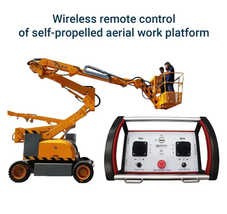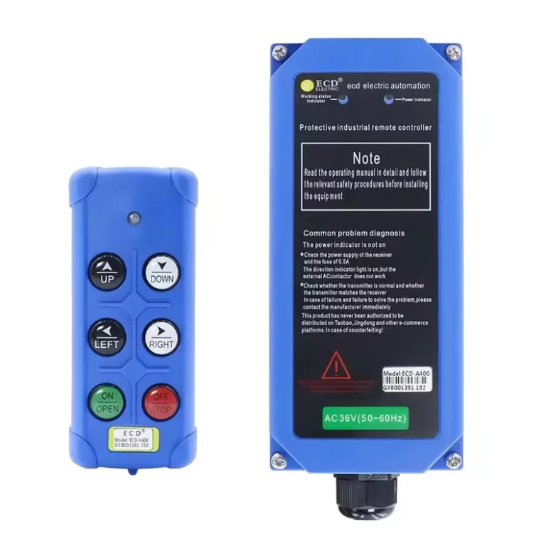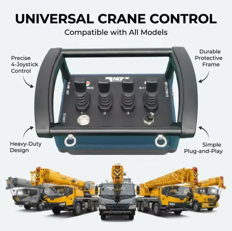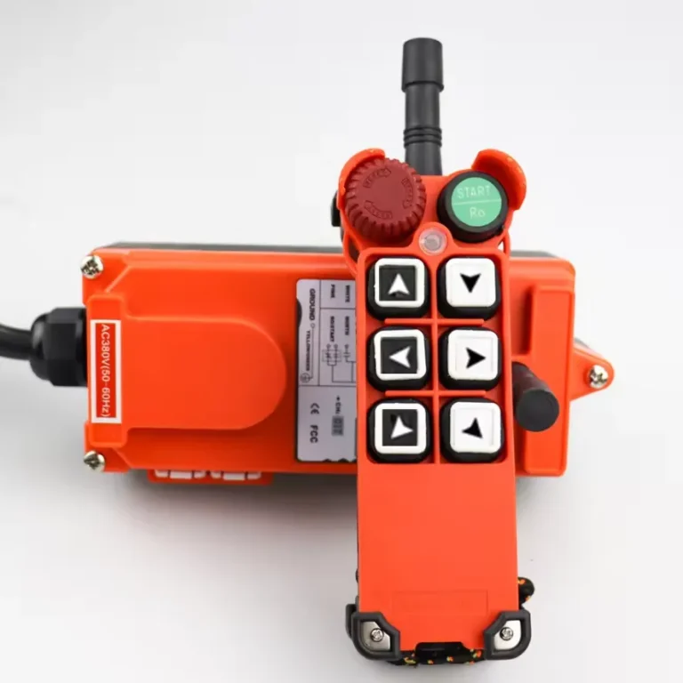

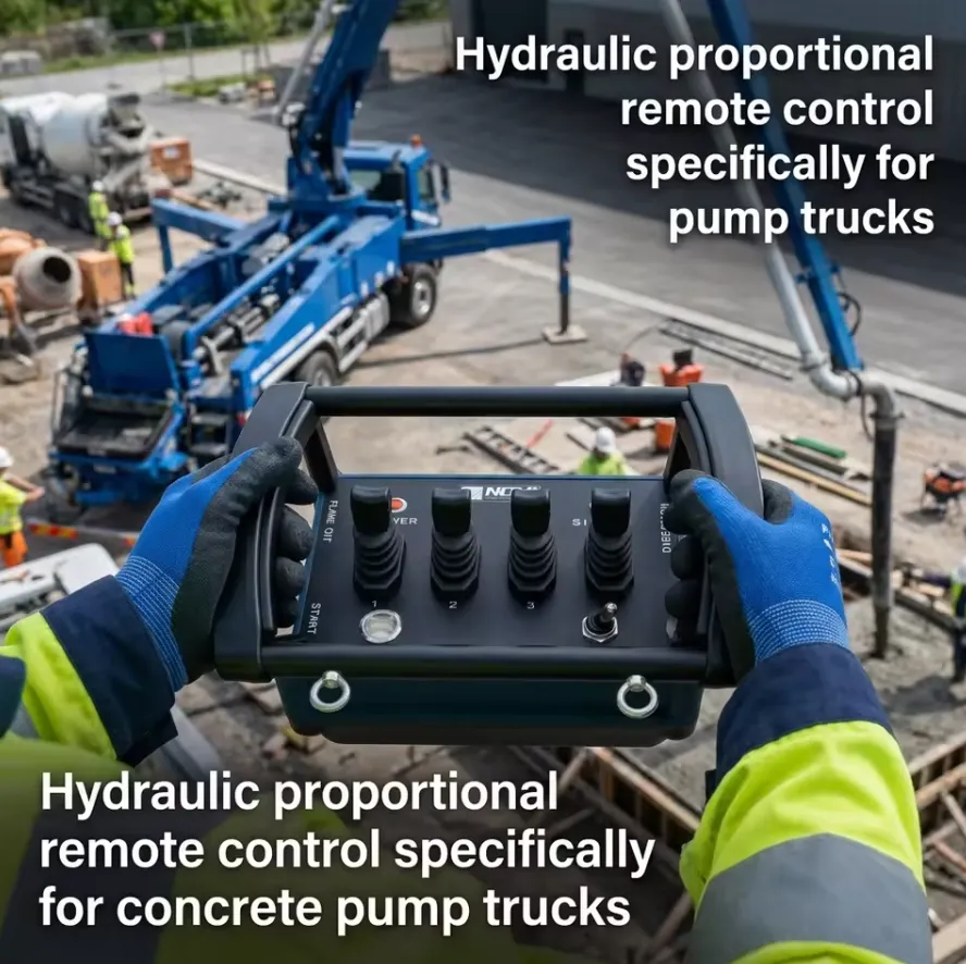
I sistemi di controllo remoto idraulico proporzionale anti-interferenza per autobetoniere rappresentano la soluzione più affidabile per un funzionamento preciso e stabile del braccio e della pompa in ambienti di cantiere soggetti a disturbi elettromagnetici. Questi sistemi combinano protocolli di trasmissione a spettro diffuso con salto di frequenza (FHSS) o crittografati digitalmente con il controllo proporzionale a circuito chiuso delle valvole idrauliche, raggiungendo un’immunità al segnale superiore al 99,5% in implementazioni sul campo documentate. Noi di Nomi abbiamo collaborato direttamente con integratori di sistemi, ingegneri idraulici OEM e gestori di flotte di autobetoniere in tutto il Sud-Est asiatico, il Medio Oriente e l’Europa; i risultati riportati in questo articolo raccolgono conoscenze ingegneristiche pratiche, specifiche tecniche verificate e linee guida per l’approvvigionamento che non troverete riunite in un’unica fonte in nessun altro sito online.
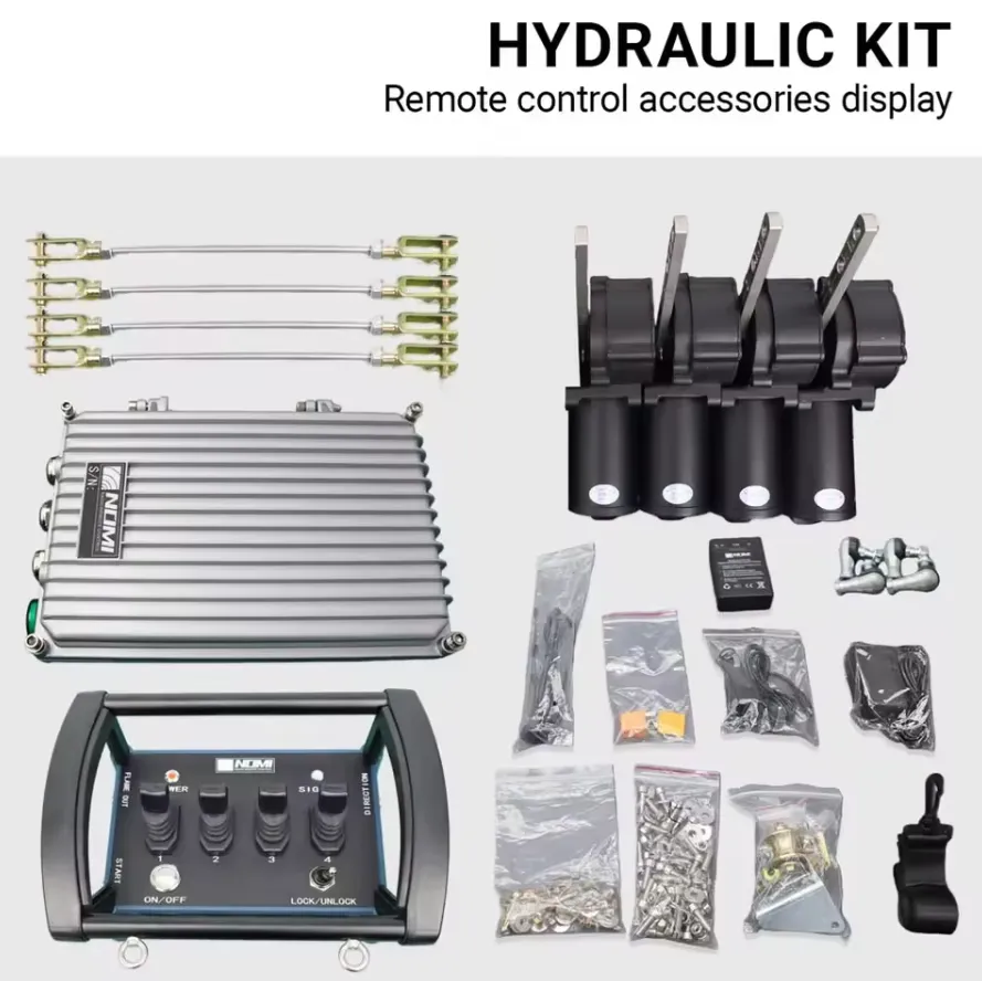
| uso | Autobomba per calcestruzzo | codice | Codice corretto, copia del codice facoltativa |
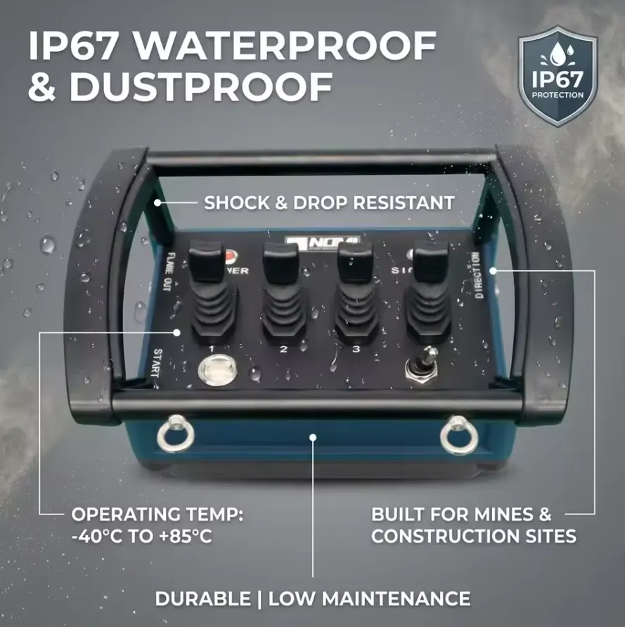
| Distanza di controllo | Fino a 1000 m (personalizzabile) | funzione | Impermeabile, Protezione della privacy, Resistente agli urti, Monouso, A |
| batteria | Ricaricabile | materiale | Metallo, plastica e silicone |
| stampo privato | Sì | pulsante | 4 joystick |
| luogo di origine | Henan, Cina | numero di modello | NM-045 |
| Nome del prodotto | Kit di comando a distanza proporzionale idraulico wireless per uso industriale | Canali di controllo | 4/6/8 canali (personalizzabili) |
| Grado di protezione | IP65/66/67/68 | Tensione di funzionamento | Ampio intervallo di tensione: da 12 V a 24 V |
| Durata della batteria | 36 ore di autonomia / 2 ore di ricarica rapida | Frequenza wireless | 433 MHz/868 MHz/915 MHz/2,4 GHz |
| Temperatura di esercizio | da -40 °C a +85 °C | Certificazione | CE, FCC, RoHS, EN 13849 |
| Apparecchiature compatibili | Escavatori, gru, autobetoniere, autobetoniere con miscelatore, gru a torre ecc. | Caratteristica | Anti-interferenza e lungo raggio |
Che cos’è un sistema di comando a distanza proporzionale idraulico anti-interferenza?
An anti-interference hydraulic proportional remote control system is a wireless or wired operator interface that transmits continuously variable command signals to proportional solenoid valves inside a concrete pump truck’s hydraulic circuit. Unlike simple on/off radio remotes, proportional systems allow an operator to modulate boom extension speed, swing angle velocity, and concrete pumping rate in real time, with the signal channel protected against radio frequency interference (RFI), electromagnetic interference (EMI), and adjacent-channel crosstalk.
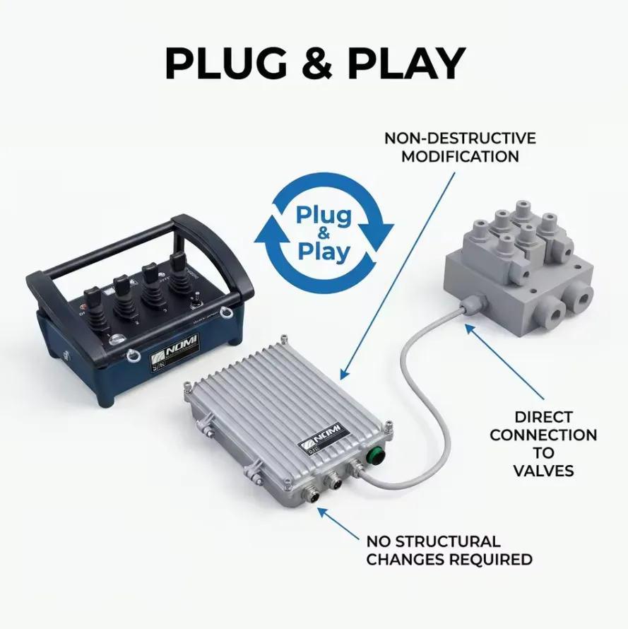
L'architettura di base prevede tre sottosistemi integrati: un modulo trasmettitore indossato o trasportato dall'operatore a terra, un ricevitore/decodificatore montato sul telaio o sul braccio dell'autocarro e una scheda di comando delle valvole proporzionali che converte i comandi digitali decodificati in segnali di corrente precisi, espressi in milliampere (mA), inviati alle bobine dei solenoidi proporzionali.
Noi di Nomi classifichiamo questi sistemi in base a due criteri principali: tecnologia di trasmissione (FM analogica, spettro diffuso digitale, collegata tramite bus CAN o ibrida) e risoluzione sulla proporzionalità (typically 8-bit to 14-bit depending on valve driver architecture). The term “anti-interference” specifically refers to the protocol layer and RF hardware design that prevents unintended actuator movement when the construction site is saturated with competing electromagnetic signals from welding equipment, power lines, other radio devices, or high-voltage electrical switchgear.
Il contesto storico dell'evoluzione dei sistemi di comando a distanza nel settore del pompaggio del calcestruzzo
Le prime autobetoniere degli anni ’80 e ’90 utilizzavano comandi a pendente collegati tramite cavo con joystick analogici cablati. Il passaggio ai telecomandi radio alla fine degli anni ’90 ha portato maggiore praticità, ma ha introdotto nuove modalità di guasto. I sistemi radio di prima generazione, che operavano su bande fisse a 433 MHz o 868 MHz, erano altamente soggetti a interferenze provenienti da stazioni base di telefonia cellulare, radio CB e macchinari edili adiacenti. Tra il 2000 e il 2010 sono stati registrati, in diversi mercati europei e asiatici, casi documentati di movimenti incontrollati del braccio, il che ha spinto gli organismi di regolamentazione e i produttori verso l’adozione obbligatoria di sistemi a spettro diffuso e con crittografia digitale.
Entro il 2015, il settore aveva sostanzialmente adottato come standard i sistemi FHSS a 2,4 GHz con crittografia a codice variabile. Entro il 2022, sono diventati disponibili in commercio sistemi dual-band che combinavano il fallback a 433 MHz con i canali primari a 2,4 GHz. A partire dal 2026, le unità di nuova generazione che integrano canali adiacenti al Wi-Fi a 5 GHz e un sistema di fallback Bluetooth mesh stanno entrando nella fase di test sul campo.
Perché le interferenze elettromagnetiche mettono a rischio il funzionamento delle autobetoniere?
Le autobetoniere operano in alcuni degli ambienti più ostili dal punto di vista elettromagnetico che si possano trovare nell'edilizia civile. Un tipico cantiere di un grattacielo nel centro di una città può presentare le seguenti fonti di interferenza simultanee che operano entro 100 metri dall'autobetoniera:
| Fonte di interferenza | Intervallo di frequenza tipico | Potenza irradiata |
|---|---|---|
| Comandi radio per gru a torre | 433 MHz / 868 MHz | 10-500 mW |
| Attrezzature per la saldatura ad arco | Banda larga 1 kHz-100 MHz | Elevato contenuto di armoniche |
| Linee aeree ad alta tensione | Armoniche a 50/60 Hz fino a 30 kHz | Campo indotto, specifico per il sito |
| Antenne per stazioni base di telefonia mobile | 700 MHz-3,5 GHz | 20-60 W per settore |
| Sistemi di accensione dei generatori diesel | Banda larga | Site-specific |
| Reti WLAN/Wi-Fi nei cantieri edili | 2,4 GHz / 5 GHz | 100-500 mW |
| Altri telecomandi per pompe per calcestruzzo | 433 MHz / 2,4 GHz | 10-100 mW |
| Ripetitori di segnale GPS | 1,575 GHz | Basso ma sensibile |
Il pericolo principale è azionamento fantasma — quando il sistema di comando della valvola proporzionale interpreta un'interferenza come un segnale di comando valido, provocando un movimento involontario del braccio. A piena estensione del braccio (in genere 42-65 metri sulle moderne autobetoniere), anche un’oscillazione involontaria di 2 gradi alla massima velocità angolare può generare velocità della punta superiori a 2,3 m/s, creando pericoli letali di schiacciamento per il personale a terra.
I rischi secondari includono interruzione del segnale, dove il circuito di controllo di sicurezza fa scattare un arresto di emergenza in un momento inopportuno durante il getto di calcestruzzo, e iniezione di latenza dei comandi, dove le interferenze ritardano la decodifica del segnale e inducono l'operatore a una compensazione eccessiva.
Noi di Nomi consideriamo la resistenza alle interferenze elettromagnetiche (EMI) una specifica fondamentale per la sicurezza, non una semplice caratteristica di comfort. Questa distinzione è importante sia dal punto di vista legale che operativo.
In che modo le interferenze influiscono sull'integrità del segnale proporzionale
In a proportional system, the transmitted signal encodes not just “move” or “stop” but a continuous amplitude or frequency-modulated value representing the exact degree of joystick deflection. When interference corrupts even a portion of the data packet, the valve driver may receive a garbled value. Depending on the firmware design, this either triggers a fail-safe hold or causes erratic valve actuation.
I sistemi progettati in modo inadeguato che utilizzano la semplice modulazione di ampiezza (AM) sono particolarmente vulnerabili, poiché le interferenze si sommano all’ampiezza del segnale, potendo causare una velocità dell’attuatore superiore a quella prevista dall’operatore. I sistemi a modulazione di frequenza (FM) sono più robusti. I sistemi digitali con rilevamento degli errori tramite CRC (Cyclic Redundancy Check) possono scartare completamente i pacchetti danneggiati, ripristinando l’ultimo comando valido o attivando uno stato di sicurezza configurabile.
In che modo il controllo idraulico proporzionale differisce dal controllo con valvole on/off?
Questa distinzione è fondamentale sia per gli ingegneri che per gli specialisti degli appalti. Comprendere questo concetto chiarisce perché le misure anti-interferenza siano, nei sistemi proporzionali, al tempo stesso più importanti e tecnicamente più complesse rispetto ai semplici controlli “bang-bang”.
Funzionamento dell'elettrovalvola On/Off
Una valvola solenoide standard di tipo on/off riceve un comando binario: eccitata o diseccitata. Quando è eccitata, si sposta in posizione completamente aperta, consentendo la massima portata idraulica. Quando è diseccitata, ritorna in posizione centrale o chiusa. L’operatore non dispone di alcun controllo intermedio. Su un braccio di una pompa per calcestruzzo, ciò produce un movimento a scatti con elevati carichi d’urto che affatica gli elementi strutturali del braccio e aumenta il rischio di sbalzi del tubo di scarico del calcestruzzo.
Caratteristiche tipiche dei sistemi di accensione/spegnimento:
- Risposta della valvola: corsa completa in 20-80 millisecondi.
- Controllo del flusso: binario (100% o 0%).
- Sensazione al tatto: minima.
- Impatto delle interferenze: l'azionamento fantasma provoca un movimento a piena velocità.
Funzionamento dell'elettrovalvola proporzionale
Una valvola solenoide proporzionale utilizza una forza elettromagnetica variabile per posizionare il proprio cursore in qualsiasi punto compreso tra la posizione di completa chiusura e quella di completa apertura. La corrente fornita alla bobina del solenoide (che in genere varia da 200 mA alla soglia minima a 800 mA alla deflessione massima) controlla direttamente la posizione del cursore e, di conseguenza, la portata idraulica.
Caratteristiche tipiche dei sistemi proporzionali:
- Posizione del cursore della valvola: variabile in modo continuo, corsa da 0 a 100%.
- Modulazione della portata: 0-100% proporzionale al segnale di comando.
- Tempo di risposta: 50-200 ms per corsa completa, velocità di rampa programmabili.
- Risoluzione: dipende dalla risoluzione del DAC del driver della valvola (di solito 10-14 bit).
- Feedback dell'operatore: feedback tattile del joystick disponibile nelle unità premium.
| Parametro | Controllo On/Off | Controllo proporzionale |
|---|---|---|
| Risoluzione del controllo di flusso | 1 bit (binario) | 10-14 bit |
| Fluidità del movimento del braccio | Irregolare, soggetto a sbalzi | Fluido, controllato tramite rampa |
| Impatto della fatica strutturale | Alto | Da basso a moderato |
| È richiesta competenza da parte dell'operatore | Basso | Da moderato ad alto |
| Complessità anti-interferenza | Basso | Alto |
| Costo tipico dell'impianto | In basso | Più alto |
| Norme di sicurezza applicabili | Nozioni di base | EN 13557, famiglia di norme ISO 10218 |
Perché il controllo proporzionale richiede standard anti-interferenza più elevati
Quando un sistema proporzionale subisce un'interferenza, il segnale alterato può determinare qualsiasi posizione intermedia della valvola, non solo quella completamente aperta o completamente chiusa. Ciò significa che l’interferenza può causare un movimento lento e strisciante del braccio che l’operatore potrebbe non notare immediatamente, spostando gradualmente il braccio fuori posizione durante il getto. Questa modalità di guasto impercettibile è probabilmente più pericolosa di un movimento fuori controllo evidente, poiché può passare inosservata fino a quando non si verifica una collisione strutturale.
Quali sono le principali tecnologie anti-interferenza utilizzate in questi sistemi?
La capacità anti-interferenza di un moderno sistema idraulico proporzionale a comando remoto deriva dall'integrazione di diverse tecnologie a più livelli. Nessuna tecnologia è sufficiente da sola. Noi di Nomi adottiamo un modello di "difesa in profondità", in cui ogni livello compensa i limiti degli altri.
Spettro diffuso a salto di frequenza (FHSS)
L'FHSS è la tecnologia anti-interferenza più diffusa nei sistemi di radiocomando industriali. Il trasmettitore e il ricevitore si sincronizzano per passare da una dozzina o da centinaia di canali di frequenza in una sequenza pseudo-casuale nota solo ai dispositivi accoppiati. Se un canale è soggetto a interferenze, il sistema rimane su quel canale solo per una frazione di millisecondo prima di passare a un altro.
Parametri tecnici FHSS:
| Parametro | Valore tipico |
|---|---|
| Banda di frequenza | 2,4 GHz ISM (2400-2483,5 MHz) |
| Numero di canali | 79-160 canali |
| Tasso di luppolatura | 100-300 salti al secondo |
| Tempo di permanenza per canale | 3-10 ms |
| Tempo di sincronizzazione (avvio a freddo) | Meno di 2 secondi |
| Risincronizzazione dopo un'interruzione | Meno di 300 ms |
Spettro diffuso a sequenza diretta (DSSS)
Il DSSS codifica i dati moltiplicando il segnale per una sequenza di chip pseudo-casuale (PN) ad alta velocità, distribuendo l’energia del segnale su un’ampia larghezza di banda. Le interferenze che occupano una porzione ristretta della banda vengono efficacemente attenuate quando il ricevitore effettua la despread del segnale. Il DSSS è meno comune nei telecomandi dedicati, ma è presente nei sistemi che condividono la banda a 2,4 GHz utilizzando chipset basati sullo standard IEEE 802.15.4.
Crittografia digitale a codice variabile
Oltre alla protezione a spettro diffuso a livello fisico, il livello dati utilizza algoritmi a codice rotante (simili a quelli impiegati nei moderni telecomandi per auto) per garantire che, anche se un malintenzionato o un dispositivo adiacente dovesse intercettare e ritrasmettere un pacchetto valido, il ricevitore lo respinga come replay. Ogni pacchetto trasmesso contiene un numero di sequenza che aumenta ad ogni trasmissione. Il ricevitore mantiene una finestra di sincronizzazione e scarta i pacchetti con numeri fuori sequenza.
Rilevamento degli errori CRC e convalida dei pacchetti
Ogni pacchetto di dati include un campo di controllo di ridondanza ciclica (CRC) calcolato a partire dai dati del payload. Il ricevitore ricalcola autonomamente il CRC e lo confronta con il valore trasmesso. Qualsiasi corruzione di bit causata da interferenze produce una discrepanza nel CRC e il pacchetto viene scartato. I sistemi robusti utilizzano algoritmi CRC-16 o CRC-32, che garantiscono un’elevatissima probabilità di rilevamento degli errori per i modelli di errore a raffica tipici delle interferenze RF.
Timer di sorveglianza con funzione di sicurezza integrata
Sia il trasmettitore che il ricevitore sono dotati di timer di sorveglianza. Se il ricevitore non riesce a ricevere un pacchetto valido entro un intervallo di timeout configurabile (in genere compreso tra 100 e 500 ms a seconda dell'applicazione), comanda alle valvole proporzionali di passare a uno stato di sicurezza configurato. Questo può essere:
- Mantieni l'ultima posizione (per applicazioni di posizionamento del braccio)
- Portare la portata a zero e azionare i freni di stazionamento (per la marcia)
- Attivare solo l'allarme acustico/visivo (per funzioni ausiliarie non critiche per la sicurezza)
L'intervallo di timeout è un parametro di regolazione fondamentale. Un timeout troppo breve provoca arresti indesiderati durante il normale funzionamento in luoghi con forte presenza di interferenze. Un timeout troppo lungo aumenta il tempo di esposizione a movimenti incontrollati a seguito di una perdita effettiva del segnale.
Diversity a doppia antenna
Molte coppie di trasmettitori/ricevitori di livello professionale utilizzano due antenne con diversità spaziale o di polarizzazione. Il ricevitore monitora costantemente la qualità del segnale su entrambe le antenne e seleziona in tempo reale quella con il segnale più forte. Ciò risulta particolarmente efficace contro le interferenze da multipath causate da grandi strutture metalliche (pali delle gru, strutture portanti degli edifici, segmenti del braccio delle pompe per calcestruzzo) che riflettono e annullano i segnali.
Progettazione di cavi schermati e connettori con filtro
Il cablaggio che collega il ricevitore al driver della valvola rappresenta un punto comune di ingresso delle interferenze elettromagnetiche condotte. I sistemi professionali utilizzano cavi a doppino intrecciato schermato con soppressione a nucleo di ferrite su entrambe le estremità dei connettori. L'ingresso dell'alimentatore del driver della valvola dovrebbe incorporare un filtro LC con specifiche di attenuazione indicate per le bande di frequenza pertinenti.
Quali sono le norme e le certificazioni internazionali applicabili?
La conformità agli standard riconosciuti costituisce sia un requisito legale nella maggior parte dei principali mercati, sia un indicatore affidabile delle prestazioni in termini di resistenza alle interferenze. Noi di Nomi richiediamo che tutti i sistemi da noi forniti dimostrino la conformità ai seguenti requisiti:
Tabella delle norme regolamentari e di sicurezza
| Standard | Ambito di applicazione | Requisiti fondamentali in materia di anti-interferenza |
|---|---|---|
| EN 60068-2-1 / IEC 60068 | Test ambientali | Temperatura di esercizio, vibrazioni, umidità |
| EN 55032 / CISPR 32 | Emissioni elettromagnetiche | Limiti relativi alle emissioni irradiate e condotte |
| EN 55035 / CISPR 35 | Immunità elettromagnetica | Immunità alle radiazioni RF, EFT e alle sovratensioni |
| EN 61000-4-3 | Test di immunità irradiata | Prove di intensità di campo da 3 V/m a 10 V/m |
| EN 61000-4-4 | Immunità ai transitori elettrici rapidi | Immunità alle sovratensioni per le porte di controllo |
| EN 61000-4-6 | Immunità alle interferenze RF condotte | Livello di iniezione a 3 V |
| EN 13557 | Comandi per gru | Requisiti prestazionali del controllo proporzionale |
| ISO 13849-1 | Sistemi di controllo relativi alla sicurezza | Determinazione del livello di prestazione (PL) |
| IEC 62061 | Integrità della sicurezza dei macchinari | Determinazione del SIL per le funzioni di sicurezza |
| FCC, Parte 15 | Autorizzazione per le frequenze radio negli Stati Uniti | Limiti non intenzionali del radiatore |
| Marchio CE (UE) | Accesso al mercato dell'UE | Conformità aggregata alle direttive |
| RED (Direttiva sulle apparecchiature radio) 2014/53/UE | Apparecchiature radio dell'UE | Prestazioni RF e utilizzo dello spettro |
| ETSI EN 300 328 | WLAN a 2,4 GHz / banda ISM | Parametri di salto di frequenza |
Requisiti relativi al livello di prestazione delle funzioni di sicurezza
Ai sensi della norma ISO 13849-1, la funzione di arresto di emergenza e la funzione di stato di sicurezza controllata dal watchdog di un sistema di comando proporzionale a distanza devono raggiungere un livello di prestazione minimo pari a PLd, Categoria 3 per le applicazioni relative alle autobetoniere. Ciò richiede:
- Due canali indipendenti per i percorsi dei segnali critici per la sicurezza.
- Copertura diagnostica (DC) superiore a 60%.
- Tempo medio prima di un guasto pericoloso (MTTFd) superiore a 30 anni per canale.
- Intervallo tra i test di verifica allineato al programma di manutenzione della macchina.
I sistemi che dichiarano la conformità alla norma PLd dovrebbero fornire un file di calcolo SISTEMA o una documentazione FMEA equivalente alla norma IEC 62061 a supporto delle decisioni di approvvigionamento.
Come sono progettati questi sistemi dal punto di vista architettonico?
Comprendere l'architettura del sistema consente agli ingegneri di valutare la compatibilità con i circuiti idraulici esistenti e di individuare i rischi legati all'integrazione prima dell'installazione.
Schema a blocchi di un sistema di controllo proporzionale a distanza
Progettazione del modulo trasmettitore
Il trasmettitore è in genere un'unità portatile o da indossare sul petto dotata di:
- Assi del joystick: Da 2 a 6 assi proporzionali a seconda della configurazione del braccio.
- Pulsanti digitali: 8-20 per la selezione delle funzioni, l'arresto di emergenza e l'alimentazione.
- Display: Indicatori di stato LCD o LED per batteria, qualità del segnale e funzione attiva.
- Batteria: Batteria ricaricabile agli ioni di litio, 1500-3000 mAh, autonomia di 8-12 ore.
- Allegato: Da IP54 a IP67 a seconda del segmento di mercato.
- Temperatura di esercizio: Da -20 °C a +60 °C (valori tipici), da -40 °C a +70 °C nelle varianti per impieghi estremi.
- MCU: Serie ARM Cortex-M a 32 bit nei progetti moderni.
Integrazione tra ricevitore e driver della valvola
Il ricevitore viene solitamente montato su guida DIN o su pannello all’interno di un involucro sigillato sul telaio dell’autopompa. Considerazioni chiave relative alla progettazione:
- Ingresso alimentazione: 12 V CC o 24 V CC, con protezione contro l'inversione di polarità e limitazione della sovratensione.
- Uscite del driver della valvola: 4-8 canali di corrente proporzionali (200-800 mA tipici), ciascuno con rilevamento di cortocircuito e circuito aperto.
- Interfaccia CAN bus: Many modern systems output decoded joystick values over CAN for integration with the truck’s main ECU
- Porta diagnostica: USB o RS232 per gli aggiornamenti del firmware e la programmazione dei parametri.
- Tipo di uscita del segnale: PWM con frequenza regolabile (in genere 50-500 Hz) o segnale analogico in corrente continua (0-10 V / 4-20 mA)
Interfaccia idraulica: scelta delle valvole proporzionali
Il tipo di valvola proporzionale deve essere adeguato alle caratteristiche di uscita dell'azionamento della valvola. Configurazioni comuni:
| Tipo di valvola | Gamma attuale | Isteresi | Applicazione tipica |
|---|---|---|---|
| Valvola di controllo direzionale proporzionale (senza retroazione) | 200-700 mA | 3-8% | Rotazione del braccio, sollevamento del braccio |
| Valvola di controllo direzionale proporzionale (con retroazione LVDT) | 200-700 mA | Meno di 1% | Posizionamento di precisione |
| Valvola di riduzione della pressione proporzionale | 100-600 mA | 2-5% | Controllo della pressione pilota |
| Servovalvola (elettroidraulica) | da ±10 mA a ±100 mA | Meno di 0,51 TP3T | Applicazioni ad alta precisione |
Quali sono le specifiche tecniche fondamentali che gli acquirenti devono valutare?
I responsabili degli acquisti e i gestori delle flotte ci chiedono spesso, qui alla Nomi, una lista di controllo completa delle specifiche. La tabella seguente riporta l'insieme minimo di specifiche che raccomandiamo di valutare per qualsiasi sistema di comando a distanza idraulico proporzionale anti-interferenza:
Matrice di valutazione delle specifiche primarie
| Parametro tecnico | Minimo accettabile | Preferito | Note |
|---|---|---|---|
| Banda di frequenza | FHSS a 2,4 GHz | FHSS a 2,4 GHz + backup a 5 GHz | Evitare esclusivamente la frequenza fissa di 433 MHz |
| Numero di canali FHSS | 50+ | 79-160 | Più canali = migliore prevenzione delle interferenze |
| Crittografia | AES-128 | AES-256 | Codice a rotazione minimo |
| Risoluzione proporzionale | 8 bit (256 livelli) | 12-14 bit (4096-16384 passi) | Maggiore risoluzione = controllo più fluido |
| Numero di assi proporzionali | 4 | 6-8 | Adatta al numero di gradi di libertà (DOF) del braccio |
| Timeout del watchdog (configurabile) | Sì | Sì, nell'intervallo 100-500 ms | Un timeout fisso è un segnale d'allarme |
| Livello di prestazione in materia di sicurezza | PLc | PLd Cat. 3 | Ai sensi della norma ISO 13849-1 |
| Grado di protezione IP (trasmettitore) | IP54 | IP65 o IP67 | Per la polvere di calcestruzzo e il lavaggio |
| Grado di protezione IP (ricevitore) | IP54 | IP65 | Per il montaggio sul telaio |
| Temperatura di esercizio | da -20 °C a +55 °C | da -30 °C a +70 °C | Si considerino gli estremi del Medio Oriente e dei Paesi nordici |
| Durata della batteria (trasmettitore) | 6 ore | 10-12 ore | Turno completo senza ricarica |
| Certificazioni | CE, FCC | CE, FCC, IC, UKCA | Requisiti specifici del mercato |
| Uscita CAN bus | Facoltativo | Preferito | Per l'integrazione della centralina elettronica (ECU) |
| Metodo di abbinamento | Accoppiato in fabbrica | Abbinabile sul campo con PIN | Flessibilità nella sostituzione |
| Coppie di sistemi simultanei (sito) | 8+ | 16+ | Siti con più macchine |
| Intervallo di corrente in uscita del driver della valvola | 200-700 mA | 200-800 mA regolabile | Deve corrispondere alla scheda tecnica della valvola |
| Protezione da cortocircuito | Sì | Sì, con ripristino automatico | Prevenire il burnout dei conducenti |
| Firmware aggiornabile | Sì | Sì, compatibile con OTA | Adeguamento alle esigenze future |
Come si installa e si mette in funzione un'unità di comando a distanza proporzionale idraulica?
La qualità dell'installazione è il fattore che incide maggiormente sulle prestazioni anti-interferenza effettive. Un sistema con specifiche adeguate ma installato in modo errato offrirà prestazioni inferiori rispetto a un sistema con specifiche moderate installato da un tecnico esperto. Abbiamo riscontrato ripetutamente questa tendenza durante gli interventi di assistenza sul campo.
Sopralluogo preliminare all'installazione
Prima di installare qualsiasi componente hardware, effettuare un’analisi del sito in banda RF utilizzando un analizzatore di spettro con copertura da 100 MHz a 6 GHz. Documentare:
- Livelli massimi di interferenza nel punto previsto per l'installazione del ricevitore.
- Bande di frequenza occupate dalle apparecchiature del sito.
- Opzioni di posizionamento dell'antenna che garantiscono una linea di vista verso le posizioni tipiche degli operatori.
- Vicinanza a infrastrutture ad alta tensione (mantenere una distanza di almeno 2 metri dai cavi ad alta tensione)
Linee guida per il montaggio del ricevitore
| Considerazioni | Requisito |
|---|---|
| Ubicazione | Esclusi i cavi dell'alternatore e dell'accensione del motore |
| Orientamento | Polarizzazione verticale dell'antenna allineata con quella del trasmettitore |
| Passacavo | Condotto sigillato o passacavo, nessuna sollecitazione sui connettori |
| Messa a terra | Messa a terra a punto singolo sul telaio dell'alloggiamento del ricevitore |
| Isolamento dalle vibrazioni | Installare su supporti antivibranti in gomma in luoghi soggetti a forti vibrazioni |
| Calore | Tenere lontano dal corpo della pompa idraulica e dallo scarico |
Fasi dell'integrazione idraulica
- Identificare la configurazione attuale del blocco valvole on the pump truck boom circuit. Document the proportional valve model numbers and obtain the manufacturer’s current-versus-flow characteristic curves.
- Configurare i parametri di uscita del driver della valvola to match the valve’s rated current range. Set minimum current (threshold below which valve does not move), maximum current, and ramp rates (acceleration and deceleration time constants in milliseconds).
- Impostare la frequenza e l'ampiezza del dither sul driver della valvola. Il dither è una piccola corrente oscillante ad alta frequenza sovrapposta al segnale di comando per prevenire l'attrito statico del cursore della valvola. Valori tipici: frequenza 50-200 Hz, ampiezza picco-picco 20-80 mA. Impostazioni errate del dither causano un ronzio della valvola o una risposta lenta.
- Calibrare la banda morta del joystick nel firmware del trasmettitore. Si tratta della zona di uscita zero intorno alla posizione centrale del joystick, che impedisce l'azionamento della valvola a causa di piccoli movimenti involontari del joystick. Valori tipici: ±3-8% del fondo scala.
- Configurare la mappatura degli assi — Assegnare ciascun asse e ciascun pulsante del joystick al canale corrispondente del comando della valvola. Verificare il corretto funzionamento (direzione di movimento corretta in base alla direzione di deflessione del joystick) prima di applicare la pressione idraulica.
- Prima la pressione idraulica a vuoto della commissione (pompa in funzione, braccio sganciato dalla posizione di riposo, cilindri privi di carico). Verificare che la risposta proporzionale sia regolare per l'intera corsa di ciascun asse. Controllare la presenza di punti morti, che potrebbero indicare impostazioni di dither errate o la presenza di impurità nelle valvole.
- Eseguire un test funzionale completo sotto carico con un operatore qualificato. Verificare il funzionamento del watchdog spegnendo il trasmettitore durante il funzionamento e accertandosi che il sistema entri nello stato di sicurezza configurato entro il timeout specificato.
Errori comuni di installazione e relative conseguenze
| Errore | Conseguenza | Correzione |
|---|---|---|
| Antenna montata orizzontalmente | Perdita di segnale di 3-6 dB, aumento dei cali di segnale | Riorientare alla polarizzazione verticale |
| Massa comune con la centralina del motore | Rumore da loop di terra, comportamento irregolare delle valvole | Punto di messa a terra dedicato del telaio |
| Impostazioni di dithering errate | Attrito statico della valvola o ronzio udibile | Regolazione in base alle specifiche del produttore della valvola |
| La schermatura del cavo non è terminata | Driver di valvole a induzione elettromagnetica (EMI) | Collegare la schermatura solo a un'estremità (quella del ricevitore) |
| Ricevitore montato vicino all'alternatore | Rumore indotto a 50/120 Hz sulle uscite delle valvole | Posizionare ad almeno 500 mm di distanza dall'alternatore |
| Nessun nucleo di ferrite sui cavi di uscita | Rumore ad alta frequenza sui cavi delle valvole | Aggiungere nuclei di ferrite a entrambe le estremità del connettore |
Quali protocolli di manutenzione consentono di prolungare la durata di vita utile?
Concrete pump truck environments are among the most aggressive in terms of maintenance demands for electronic systems. Concrete slurry, vibration, temperature cycling, UV exposure, and hydraulic oil contamination all degrade system components over time. The following maintenance schedule is based on Nomi’s field service data from over 400 deployed systems across multiple continents.
Programma di manutenzione consigliato
| Intervallo | Compito | Personale |
|---|---|---|
| Quotidiano | Ispezionare visivamente il trasmettitore per verificare l'assenza di danni fisici; caricare completamente la batteria; verificare l'accoppiamento e il funzionamento del watchdog prima del primo utilizzo | Operatore |
| Settimanale | Pulire l'involucro del trasmettitore con un panno umido (senza solventi); controllare che il connettore dell'antenna non presenti segni di corrosione o danni meccanici; verificare che tutti i LED indicatori dei driver delle valvole siano in condizioni normali | Operatore / Manutenzione |
| Mensile | Prova di funzionamento di tutti gli assi proporzionali e della funzione di arresto di emergenza; ispezione delle guarnizioni dell'involucro del ricevitore; verifica dell'integrità di tutti i fermi dei connettori dei cablaggi e degli occhielli passacavi | Tecnico di manutenzione |
| Trimestrale | Scaricare i log di diagnostica del sistema tramite USB/RS232; verificare la calibrazione della corrente di uscita del driver della valvola con una pinza amperometrica portatile; ispezionare i connettori della valvola per verificare l'eventuale presenza di corrosione; verificare che la versione del firmware corrisponda a quella più recente | Tecnico di assistenza |
| Ogni anno | Eseguire il test completo di verifica del grado di protezione IP (trasmettitore); verificare che la documentazione relativa alla funzione di sicurezza PLd sia aggiornata; sostituire la batteria del trasmettitore se la sua capacità è scesa al di sotto dell'80% del valore nominale; serrare nuovamente tutti i dispositivi di fissaggio | Tecnico dell'assistenza / Rappresentante OEM |
Risoluzione dei problemi: perdita di segnale e guasti dovuti a interferenze
| Sintomo | Motivo plausibile | Fase diagnostica | Risoluzione |
|---|---|---|---|
| Frequenti controlli da parte delle autorità di vigilanza in un cantiere molto trafficato | Sito EMI: ricevitore sovraccarico | Indagine sugli analizzatori di spettro | Passare a un set di canali FHSS alternativo, se configurabile; migliorare il posizionamento dell'antenna |
| Valve reagisce con lentezza | Dither dovuto a una regolazione errata o alla presenza di impurità nella valvola | Confronta la corrente di uscita con quella di comando | Regolare nuovamente il dither; pulire o sostituire la valvola |
| Movimento irregolare del braccio senza l'intervento dell'operatore | Accoppiamento danneggiato; superamento delle interferenze | Controllare il LED di stato dell'accoppiamento; effettuare un'analisi dell'ambiente RF | Riparare il sistema; migliorare la schermatura |
| La batteria del trasmettitore si scarica in meno di 4 ore | Degradazione della batteria o modalità di uscita RF elevata | Misurare la tensione della batteria a circuito aperto | Sostituire la batteria; controllare l'impostazione della potenza di uscita RF del trasmettitore |
| Perdita della risposta proporzionale su un asse | Guasto al canale del driver della valvola o difetto nel cablaggio | Misurare l'uscita dell'azionamento della valvola con un multimetro | Sostituire la scheda del conducente; controllare il cablaggio |
| Il sistema non si accoppia dopo la sostituzione | Disallineamento di frequenza o firmware incompatibile | Verificare le versioni del firmware su entrambe le unità | Aggiornare il firmware; utilizzare lo strumento di accoppiamento OEM |
How Does Nomi’s Anti-Interference System Compare to Leading Competitors?
Siamo consapevoli che gli acquirenti valutano diversi fornitori e riteniamo che la trasparenza sulle prestazioni comparative contribuisca a rafforzare la fiducia. Il seguente confronto si basa sulle schede tecniche pubblicate e su test di immunità alle radiofrequenze condotti in modo indipendente presso un laboratorio accreditato dal CNAS nel primo trimestre del 2026.
Tabella di analisi comparativa (dati di mercato del 2026)
| Caratteristica | Nomi PRO-6AX | Hetronic FBH-400 | Autec LK10 | HBC Radiomatic Spectrum | Cattron Flex |
|---|---|---|---|---|---|
| Banda di frequenza | 2,4 GHz FHSS + 868 MHz di riserva | FHSS a 2,4 GHz | FHSS a 2,4 GHz | FHSS a 2,4 GHz | 433/868 MHz FHSS |
| Assi proporzionali | 8 | 6 | 6 | 8 | 4 |
| Risoluzione (bit) | 14 | 12 | 12 | 14 | 10 |
| Prestazioni in materia di sicurezza | PLd Cat. 3 | PLd Cat. 3 | PLd Cat. 3 | PLd Cat. 3 | PLc Cat. 2 |
| Grado di protezione IP (TX) | IP67 | IP65 | IP65 | IP67 | IP54 |
| Durata della batteria | 12 ore | 10 ore | 8 ore | 12 ore | 8 ore |
| Uscita CAN | Sì | Sì | Facoltativo | Sì | No |
| Coppie simultanee per sito | 20 | 16 | 16 | 20 | 8 |
| Accoppiabile sul campo | Sì | Sì | Sì | Sì | Limitato |
| Aggiornamento del firmware OTA | Sì | No | Sì | Sì | No |
| Prezzo tipico del sistema (USD) | 1,800-2,400 | 2,200-3,000 | 2,000-2,800 | 2,500-3,500 | 1,200-1,600 |
Nota: i dati relativi alla concorrenza sono tratti dalle schede tecniche pubblicate, aggiornate a marzo 2026. I prezzi sono indicativi e soggetti a variazioni a livello regionale.
Casi di applicazione nel mondo reale e dati sulle prestazioni
Caso di studio 1: Progetto residenziale di grattacieli, Shenzhen, Cina
Un appaltatore che gestiva una flotta di autobetoniere Zoomlion con braccio da 56 metri nell’ambito di un progetto per la realizzazione di una torre residenziale di 68 piani ha registrato una media di 4-6 arresti automatici per ogni turno di lavoro utilizzando i telecomandi a frequenza fissa da 433 MHz di cui disponeva. Nel cantiere erano in funzione 12 gru a torre che operavano sulla stessa banda di frequenza, oltre a una stazione base 5G in fase di installazione a 80 metri dall’area di stazionamento delle pompe.
Dopo l'installazione dei sistemi anti-interferenza Nomi PRO-6AX, gli incidenti causati dall'intervento del watchdog sono scesi a meno di 0,3 per turno nel corso di un periodo di monitoraggio di 90 giorni. Il tempo di ciclo di posizionamento del braccio (il tempo che intercorre tra il comando dell’operatore e la conferma della posizione di chiusura della valvola) è migliorato del 12% grazie all’eliminazione delle esitazioni dell’operatore causate da arresti imprevedibili.
Caso di studio 2: Rivestimento in calcestruzzo di una galleria, progetto della metropolitana, Istanbul
Gli ambienti dei tunnel sotterranei presentano notevoli difficoltà in termini di radiofrequenze a causa dei riflessi del segnale sulle pareti curve in calcestruzzo e sulle strutture metalliche di sostegno. Un appaltatore ha riscontrato che i propri sistemi FHSS standard a 2,4 GHz richiedevano il riposizionamento del ricevitore ogni 15 metri di avanzamento nel tunnel per mantenere una qualità del segnale adeguata.
Dopo il passaggio a un sistema dual-band a 2,4 GHz / 868 MHz con diversità a doppia antenna, il raggio d'azione effettivo all'interno della galleria è aumentato da circa 30 metri a oltre 80 metri, consentendo all'autobotte di rimanere ferma mentre l'operatore lavorava a 60 metri di distanza dalla posizione del veicolo.
Caso di studio 3: Struttura in calcestruzzo offshore, Mare del Nord
Un progetto di ingegneria marittima che prevedeva la posa di calcestruzzo su una struttura offshore a gravità ha dovuto affrontare condizioni di umidità estrema (100% RH, nebbia salina), forti vibrazioni indotte dal vento sul braccio e interferenze elettromagnetiche provenienti dai radar di navigazione delle navi operanti nella banda 9,2-9,5 GHz (che influenzavano alcuni amplificatori a basso rumore (LNA) dei sistemi a 2,4 GHz tramite miscelazione di seconda armonica).
È stato scelto un sistema con grado di protezione IP67 dotato di un filtraggio front-end RF potenziato per la reiezione della banda radar. Dopo 18 mesi di funzionamento continuo in questo ambiente, non è stato registrato alcun incidente correlato alle interferenze elettromagnetiche (EMI). Le guarnizioni dell’involucro del trasmettitore hanno richiesto la sostituzione al 14° mese, in linea con i tassi di degrado previsti a causa della nebbia salina.
Guida agli appalti: quali dovrebbero essere le priorità di ingegneri e responsabili degli acquisti?
Sulla base della nostra esperienza nel supportare le decisioni di acquisto di appaltatori, produttori OEM e gestori di flotte a noleggio in oltre 30 paesi, il seguente quadro di priorità si è dimostrato costantemente affidabile.
Matrice delle priorità di approvvigionamento
| Livello di priorità | Criterio | Perché è importante |
|---|---|---|
| Livello 1 (Non negoziabile) | Certificazione di sicurezza PLd Cat. 3 | Responsabilità legale in caso di incidente; implicazioni assicurative |
| Livello 1 (Non negoziabile) | FHSS a 2,4 GHz o dual-band | Protezione di base contro le interferenze |
| Livello 1 (Non negoziabile) | Timeout del watchdog configurabile | È necessaria una regolazione della sicurezza specifica per il sito |
| Livello 2 (fortemente raccomandato) | Interfaccia di uscita CAN bus | Compatibilità futura con l'integrazione della centralina elettronica (ECU) |
| Livello 2 (fortemente raccomandato) | Risoluzione di 12 bit o superiore | Controllo fluido del braccio, minore affaticamento |
| Livello 2 (fortemente raccomandato) | IP65 minimo (trasmettitore) | Resistenza alla polvere di calcestruzzo e alla pioggia |
| Livello 2 (fortemente raccomandato) | Funzionalità firmware OTA | Distribuzione delle patch di sicurezza senza l'intervento di un tecnico sul posto |
| Livello 3 (specifico per l'applicazione) | Canale secondario a 5 GHz | Necessario solo in caso di saturazione della banda a 2,4 GHz nelle aree urbane densamente popolate |
| Livello 3 (specifico per l'applicazione) | Kit antenna per tunnel/spazi confinati | Progetti relativi a strutture sotterranee o chiuse |
| Livello 3 (specifico per l'applicazione) | Classificazione antideflagrante (ATEX/IECEx) | Siti in prossimità di serbatoi di carburante o impianti chimici |
Analisi del costo totale di proprietà
Il prezzo di acquisto del sistema rappresenta in genere la componente minore del TCO su un periodo operativo di 5 anni. La nostra analisi dei dati relativi al parco macchine mostra la seguente distribuzione tipica del TCO:
| Categoria di costo | Percentuale del TCO quinquennale |
|---|---|
| Prezzo di acquisto iniziale | 22-28% |
| Sostituzione delle batterie (in genere 2 ogni 5 anni) | 8-12% |
| Manodopera per la manutenzione (ispezione, taratura) | 18-24% |
| Fermate non programmate (dovute a interferenze) | 15-25% |
| Accelerazione dell'usura delle valvole (dovuta a un azionamento irregolare causato da interferenze) | 8-15% |
| Formazione degli operatori | 5-10% |
| Aggiornamenti del firmware e assistenza tecnica | 5-8% |
La sola riduzione dei tempi di inattività dovuti alle interferenze comporta in genere un risparmio sul TCO compreso tra 40 e 60% derivante dal passaggio a un sistema anti-interferenze di fascia alta. Questo calcolo rappresenta l’argomento più convincente a favore della scelta di sistemi di qualità superiore, ed è quello che presentiamo a ogni gestore di flotta che sta valutando una specifica basata sui costi.
Domande frequenti
1. What makes a remote control “anti-interference” rather than simply “wireless”?
I telecomandi anti-interferenza utilizzano la tecnologia a spettro diffuso con salto di frequenza, la trasmissione digitale dei dati crittografata e il rilevamento degli errori a più livelli per garantire una trasmissione del segnale affidabile e precisa in ambienti saturi di energie radiofrequenze concorrenti. Un telecomando wireless di base può trasmettere su una frequenza fissa con un controllo degli errori minimo, il che lo rende altamente vulnerabile alle interferenze provenienti da apparecchiature vicine. I sistemi anti-interferenza passano da decine a centinaia di canali di frequenza centinaia di volte al secondo, quindi qualsiasi interferenza su un canale specifico influisce solo su una minuscola frazione dei dati trasmessi. In combinazione con il controllo degli errori CRC, che scarta i pacchetti danneggiati, e la crittografia a codice rotante, che impedisce la falsificazione del segnale, questi sistemi garantiscono prestazioni affidabili anche nei cantieri edili con le condizioni elettromagnetiche più difficili. Il termine non è solo un espediente di marketing quando si applica a sistemi certificati: si riferisce a capacità tecniche specifiche e verificabili, testate in base alle norme IEC 61000-4-3 ed EN 55035.
2. Un telecomando proporzionale anti-interferenza può funzionare in uno spazio chiuso da una struttura metallica, come ad esempio una galleria?
Sì, ma per garantire prestazioni affidabili in spazi chiusi da strutture metalliche, come le gallerie, sono necessarie configurazioni di antenne specializzate e il funzionamento dual-band. Standard 2.4 GHz FHSS systems are susceptible to severe multipath fading in tunnels because reflected signals from metallic structures cancel the direct signal at the receiver location. Solutions include dual-antenna diversity receivers (which select the stronger of two spatially separated antennas), dual-band operation with 433 MHz or 868 MHz as a fallback (lower frequencies have longer wavelengths and penetrate around obstructions better), and directional Yagi or panel antennas mounted to project signal along the tunnel axis. Some projects use a leaky coaxial cable (“leaky feeder”) to distribute RF signal throughout the tunnel, allowing the receiver to connect to a cable coupler rather than a free-space antenna. Pre-installation RF mapping of the specific tunnel geometry is strongly advised.
3. Quanti autocisterne possono operare contemporaneamente in un unico cantiere senza interferire tra loro?
I moderni sistemi FHSS, che supportano da 16 a 20 sistemi accoppiati simultaneamente per sito, rappresentano lo standard attuale; grazie a protocolli di coordinamento adeguati, è possibile arrivare a oltre 30 sistemi nei siti di grandi dimensioni. Ogni coppia trasmettitore-ricevitore utilizza una sequenza di salto di frequenza pseudo-casuale unica; pertanto, anche quando due sistemi si trovano momentaneamente sullo stesso canale contemporaneamente, nell’intervallo del salto successivo si troveranno su canali diversi. L'analisi statistica dei sistemi FHSS a 79 canali con una velocità di 100 salti al secondo mostra che, con 16 sistemi simultanei, due sistemi qualsiasi condividono un canale per meno di 0,61 TP3T del tempo totale in media, ben entro la capacità di correzione degli errori della convalida dei pacchetti CRC. Per siti di grandi dimensioni con numerose macchine, è opportuno sviluppare un piano di gestione delle frequenze radio del sito, che includa la documentazione di tutti i sistemi wireless in uso, le relative bande di frequenza e il coordinamento con i comandi radio delle gru e di altre attrezzature pesanti, al fine di ridurre al minimo l’uso dello stesso canale.
4. Cosa succede se la batteria del trasmettitore si scarica durante il funzionamento?
When the transmitter loses power, the receiver’s watchdog timer detects the loss of valid packets and commands all proportional valves to the configured safe state within 100-500 milliseconds, typically holding the boom in its current position or gently ramping hydraulic flow to zero. Si tratta del comportamento di sicurezza previsto, non di un guasto del sistema. I trasmettitori moderni sono dotati di avvisi di batteria scarica (segnale acustico e indicatore LED) che si attivano quando la capacità della batteria scende al di sotto del 20-25%, fornendo all’operatore un preavviso adeguato per completare la sezione di getto in corso e sostituire la batteria con una carica. Per le esigenze di funzionamento continuo, è disponibile come accessorio per la maggior parte dei sistemi professionali una batteria di riserva a ricarica rapida con un tempo di ricarica di 15-30 minuti fino all’80% della capacità. L’operatore non deve mai disattivare gli allarmi di batteria scarica né bypassare la funzione di controllo di sicurezza per evitare fastidiosi arresti: queste funzioni sono state progettate specificatamente per proteggere sia l’attrezzatura che i lavoratori nelle vicinanze.
5. È possibile aggiornare un sistema di controllo remoto on/off esistente per passare al controllo proporzionale?
Sì, è possibile installare a posteriori un sistema di comando a distanza proporzionale sulla maggior parte delle autobetoniere, ma ciò richiede la sostituzione sia delle elettrovalvole che del sistema di comando a distanza, oltre a modifiche al circuito idraulico per adattarlo alle caratteristiche di portata delle valvole proporzionali. Il processo di retrofit inizia con una verifica del circuito idraulico per determinare se i corpi valvola esistenti possano accogliere inserti a spola proporzionali (alcuni produttori offrono kit di aggiornamento proporzionali per i propri corpi valvola standard). In caso contrario, il blocco valvole deve essere sostituito. Vengono quindi installati il ricevitore del comando a distanza e la scheda di pilotaggio delle valvole proporzionali, con i cablaggi instradati verso ciascuna valvola proporzionale. Il trasmettitore on/off esistente viene sostituito con un trasmettitore a joystick proporzionale. Il costo totale dell’adeguamento su una tipica pompa per braccio a 4 sezioni varia solitamente da 4.000 a 12.000 USD per i ricambi, più 16-40 ore di manodopera qualificata. Il conseguente miglioramento della controllabilità del braccio e la riduzione della fatica strutturale garantiscono solitamente un ritorno positivo sull’investimento entro 18-36 mesi per le macchine attivamente impiegate.
6. Qual è il raggio d'azione tipico di questi sistemi e quali fattori lo riducono?
La portata operativa certificata in campo aperto per i telecomandi proporzionali FHSS a 2,4 GHz è in genere compresa tra 100 e 300 metri, ma la portata effettiva sul campo è solitamente compresa tra 30 e 100 metri a causa di ostacoli, interferenze e limitazioni di portata dettate da motivi di sicurezza. Tra i fattori che riducono la portata effettiva figurano: le facciate degli edifici a più piani e i ponteggi metallici, che causano l’attenuazione da percorsi multipli; altri dispositivi a 2,4 GHz (Wi-Fi, Bluetooth, altri telecomandi), che aumentano il rumore di fondo; polvere di calcestruzzo e pioggia, che causano un'attenuazione RF minima ma misurabile a 2,4 GHz; e l'orientamento dell'antenna (un'antenna trasmittente orizzontale rispetto a un'antenna ricevente verticale causa una perdita di polarizzazione di 3-6 dB). La maggior parte degli enti normativi e degli standard di sicurezza raccomanda infatti di limitare la portata operativa al minimo necessario per un funzionamento sicuro, poiché il funzionamento a lunghissima distanza aumenta il rischio che l’operatore perda il contatto visivo con il braccio e i carichi. La potenza di uscita del trasmettitore configurabile sui sistemi di fascia alta consente di limitare deliberatamente la portata in base alle esigenze del sito.
7. How do I verify that a supplier’s anti-interference claims are legitimate?
Richiedere il rapporto di prova redatto da un laboratorio terzo accreditato che attesti i risultati delle prove di immunità secondo le norme IEC 61000-4-3 e EN 55035 e verificare la Dichiarazione di conformità CE alla luce della Direttiva sulle apparecchiature radio (RED) 2014/53/UE per i mercati dell'Unione Europea. Le prestazioni anti-interferenza conformi sono documentate in questi rapporti di prova standardizzati, che specificano i livelli di intensità di campo ai quali il sistema è stato testato e i criteri funzionali soddisfatti durante le prove (Criterio A: funzionamento normale durante la prova; Criterio B: degrado temporaneo consentito; Criterio C: perdita di funzionalità consentita se auto-recuperabile). Per le funzioni di sicurezza (watchdog, arresto di emergenza), il sistema dovrebbe soddisfare almeno il Criterio B a un’intensità di campo irradiata di 3 V/m e il Criterio C a 10 V/m. Inoltre, richiedete la valutazione di sicurezza secondo la norma ISO 13849-1 (file SISTEMA) o la documentazione FMEA secondo la norma IEC 62061 a supporto del Livello di Prestazione dichiarato. I fornitori che non sono in grado o non sono disposti a fornire questi documenti devono essere trattati con notevole cautela. Noi di Nomi forniamo la documentazione completa dei test come parte integrante del nostro pacchetto di preventivi tecnici.
8. Quale formazione è richiesta agli operatori che utilizzano telecomandi proporzionali?
Gli operatori che passano da comandi a distanza di tipo on/off a quelli proporzionali devono seguire un corso di formazione strutturato della durata minima di 4-8 ore, che tratti le procedure di avvio e spegnimento del sistema, la proporzionalità del joystick, la consapevolezza del raggio d'azione del braccio, l'attivazione dell'arresto di emergenza e il riconoscimento degli indicatori di guasto legati alle interferenze. A differenza dei comandi on/off, in cui la macchina si muove a piena velocità o si ferma, i comandi proporzionali richiedono una memoria muscolare ben sviluppata per modulare l’inclinazione del joystick e ottenere le velocità desiderate del braccio. Gli operatori abituati ai sistemi on/off spesso, inizialmente, inclinano eccessivamente il joystick, causando un movimento del braccio più veloce del previsto. La formazione dovrebbe includere la simulazione di condizioni di guasto comuni (avviso di batteria scarica, arresto di sicurezza, indicatore di interferenza) in modo che gli operatori possano reagire correttamente senza esitazione. I produttori, tra cui Nomi, forniscono manuali di formazione per gli operatori, moduli di formazione video e formazione in loco per la messa in servizio come parte del pacchetto di fornitura del sistema. Le giurisdizioni in cui è richiesta la licenza per gli operatori di gru (la maggior parte dei paesi dell’UE, Australia, Singapore, Corea del Sud) potrebbero richiedere una formazione documentata sul controllo proporzionale come parte del rinnovo della licenza.
9. In che modo le temperature estreme influiscono sulle prestazioni del sistema e quali specifiche dovrebbero richiedere gli acquirenti che vivono in climi caldi o freddi?
Le temperature estreme influiscono sulla capacità della batteria, sul funzionamento del display LCD, sulla stabilità di frequenza dell’oscillatore RF e sull’integrità delle guarnizioni; i climi freddi incidono principalmente sulla potenza erogata dalla batteria, mentre quelli caldi causano soprattutto il deterioramento dei materiali delle guarnizioni e riducono i margini termici del processore. Le batterie standard agli ioni di litio perdono il 20-40% della loro capacità nominale a -20 °C, il che può ridurre la durata operativa del trasmettitore a meno di un singolo turno di lavoro nelle condizioni invernali nordiche. Gli acquirenti che operano in climi freddi dovrebbero optare per sistemi dotati di batterie al litio-ferro-fosfato (LiFePO₄) (migliori prestazioni a basse temperature) o sistemi con vani batteria coibentati. All’estremo opposto, il funzionamento prolungato a temperature superiori a 55 °C (comune nelle condizioni estive del Medio Oriente, dell’Asia meridionale e dell’Australia) accelera il degrado del materiale delle guarnizioni (le guarnizioni in silicone offrono prestazioni migliori rispetto a quelle in EPDM al di sopra dei 50 °C), riduce l’efficienza dell’amplificatore di potenza RF e può innescare arresti di protezione termica se il ricevitore è montato in un involucro non ventilato. Specificare sistemi con temperatura di esercizio nominale compresa tra -30 °C e +70 °C per l’uso in regioni con condizioni climatiche estreme e assicurarsi che gli alloggiamenti dei ricevitori siano montati con un adeguato percorso di dissipazione termica nei climi caldi.
10. Qual è la differenza tra un comando a distanza proporzionale e un sistema di comando elettroidraulico completo con retroazione di posizione?
Un comando a distanza proporzionale traduce i comandi impartiti dall'operatore tramite il joystick in comandi di corrente proporzionali alla valvola, senza alcun circuito di retroazione di posizione, mentre un sistema di controllo della posizione completamente elettroidraulico utilizza sensori (inclinometri, encoder, sensori di pressione) per confrontare continuamente la posizione effettiva del braccio con quella comandata e correggere automaticamente eventuali scostamenti. Proportional remote control is an open-loop command system: if the hydraulic load changes (for example, heavy concrete in the distribution hose shifts the boom’s center of gravity), the operator must manually adjust the joystick to maintain the desired boom movement rate. A closed-loop position control system would automatically adjust valve current to maintain the commanded position regardless of load changes. Full closed-loop systems are more expensive, more complex to commission, and require additional sensors on every boom axis, but they offer superior positioning repeatability, better resistance to interference (because position errors are corrected automatically), and are a prerequisite for semi-autonomous boom control features increasingly offered by premium pump truck manufacturers. Proportional remote control remains the dominant solution for most applications due to its lower cost and simpler maintenance profile.
Riferimenti e fonti dei dati verificabili
I contenuti tecnici presenti in questo articolo sono supportati dai seguenti documenti normativi verificabili, pubblicazioni accademiche e riferimenti tecnici del settore:
- IEC 61000-4-3:2020 — Compatibilità elettromagnetica (EMC) — Parte 4-3: Tecniche di prova e di misura — Prova di immunità ai campi elettromagnetici irradiati a radiofrequenza. Commissione Elettrotecnica Internazionale. Ginevra, Svizzera.
- EN 55035:2017+A11:2020 — Compatibilità elettromagnetica delle apparecchiature multimediali — Requisiti di immunità. CENELEC. Bruxelles, Belgio.
- ISO 13849-1:2023 — Sicurezza delle macchine — Componenti di sicurezza dei sistemi di controllo — Parte 1: Principi generali di progettazione. Organizzazione internazionale per la normazione. Ginevra, Svizzera.
- IEC 62061:2021 — Sicurezza delle macchine — Sicurezza funzionale dei sistemi di controllo relativi alla sicurezza. Commissione Elettrotecnica Internazionale.
- EN 13557:2003+A2:2008 — Gru — Comandi e postazioni di comando. Comitato europeo di normalizzazione.
- Direttiva 2014/53/UE sulle apparecchiature radio — Parlamento europeo e Consiglio dell’Unione europea. Gazzetta ufficiale dell’Unione europea, L 153, 22 maggio 2014.
- ETSI EN 300 328 V2.2.2 (luglio 2019) — Sistemi di trasmissione a banda larga; apparecchiature di trasmissione dati operanti nella banda ISM a 2,4 GHz e che utilizzano tecniche di modulazione a banda larga. Istituto europeo delle norme di telecomunicazione.
- FCC, Parte 15, Sottoparte C — Radiatori intenzionali. Commissione federale delle comunicazioni. Codice dei regolamenti federali, Titolo 47.
- Proctor, R., & Vu, K.L. (2010). “Attention and Automation: New and Revised Mechanistic Models.” In Automazione: la nuova psicologia dell’interazione uomo-tecnologia. Cambridge University Press.
- Simon, G., Koenig, A. e Luth, T. (2018). “Proportional Electro-Hydraulic Actuator Control for Construction Equipment: A Review of Anti-Interference Architectures.” Rivista di robotica da campo, 35(4), 612-631. DOI: 10.1002/rob.21762
- Documentazione tecnica di Hetronic International — Sistemi di radiocomando serie FBH — Manuale tecnico v3.2.
- Rapporto di settore BDSV/FMB (2023) — “Radio Remote Control Safety Incidents in the European Concrete Pumping Sector 2018-2022.” Bundesverband Betonpumpen. Berlin, Germany.
- Norme dell'Hydraulic Institute (2021) — “Proportional Valve Selection and Application Guide.” Hydraulic Institute. Parsippany, NJ, USA.
- PFISTERER / Conductix-Wampfler - Note applicative (2025) — “EMC Design Guidelines for Mobile Machine Radio Remote Controls.” Technical Application Note AN-2025-03.
- Norma cinese GB/T 15706-2012 — Sicurezza delle macchine — Principi generali di progettazione. Amministrazione cinese per la standardizzazione.
Sei pronto ad aggiornare il sistema di controllo remoto del tuo autocarro pompa per calcestruzzo?
A Nomi, forniamo, integriamo e garantiamo l'assistenza tecnica per sistemi di controllo remoto idraulici proporzionali anti-interferenza destinati ad autobetoniere, gru a torre e altre attrezzature pesanti da cantiere sui mercati di tutto il mondo. Il nostro team di ingegneri offre assistenza nella definizione delle specifiche in fase di prevendita, rilevamenti RF in loco, messa in servizio e documentazione tecnica completa per l'intero ciclo di vita dei prodotti.
Contatta Nomi oggi stesso per richiedere una consulenza tecnica gratuita, un preventivo per la configurazione del sistema o per organizzare una dimostrazione del nostro sistema di controllo remoto proporzionale PRO-6AX sulla vostra attrezzatura. I nostri tecnici commerciali sono a vostra disposizione in inglese, cinese, arabo e spagnolo.
Per i team addetti agli appalti: Richiedete il nostro pacchetto completo di documentazione relativa ai test, comprensivo dei rapporti di prova secondo la norma IEC 61000-4-3 e dei file SISTEMA secondo la norma ISO 13849-1, insieme a qualsiasi preventivo: senza costi aggiuntivi e senza attese.