

أنظمة التحكم في الرافعات العلوية والرافعات
المنتجات
المنتجات
اتصل بنا
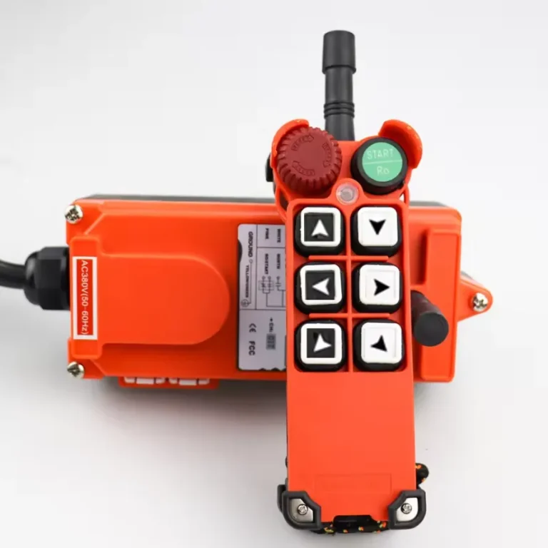

يؤدي تحديث أنظمة التحكم في الرافعات العلوية والرافعات اليدوية إلى انخفاض مؤكد في حوادث الوفاة في أماكن العمل، وأوقات التعطل غير المخطط لها، وتكاليف التشغيل على مدار دورة الحياة، شريطة أن يتم التنفيذ وفقًا للمعايير الحالية ASME B30.2 وOSHA 1910.179 وEN 13001. تقوم المنشآت التي تقوم بتحديث أنظمة التحكم المعلقة القديمة التي تعتمد على منطق المرحلات إلى وحدات تحكم بمحركات التردد المتغير (VFD) المزودة بمرحلات أمان قابلة للبرمجة وواجهات لاسلكية بتخفيض معدلات الإصابات المرتبطة بالرافعات بنسبة تتراوح بين 35% و55%، وخفض نفقات الصيانة السنوية بنسبة تتراوح بين 20% و40%، استنادًا إلى معايير الصناعة الموثقة. في Nomi، قمنا بدعم مشاريع التحديث في مصانع الصلب ومصانع السيارات ومحطات الموانئ، ويعكس هذا الدليل تلك الخبرة التقنية العملية.
ما الذي يميز نظام التحكم الحديث في الرافعات العلوية؟
يُعد نظام التحكم الحديث في الرافعات العلوية مجموعة متكاملة من مكونات الأجهزة والبرمجيات التي تعمل على ترجمة أوامر المشغل إلى حركات دقيقة وآمنة وقابلة للتكرار للرافعة، مع المراقبة المستمرة للمعلمات الميكانيكية والكهربائية لمنع حدوث أي ظروف غير آمنة. ويغطي هذا النظام سلسلة الإشارات بالكامل بدءًا من جهاز إدخال المشغل، مرورًا بوحدة التحكم المنطقية القابلة للبرمجة (PLC) أو بنية مرحلات الأمان، وصولًا إلى خرج محرك الدفع، ثم العودة عبر ردود فعل المستشعرات إلى واجهة المشغل.
أدى الانتقال من المقومات الكهروميكانيكية التقليدية ووحدات التحكم الأسطوانية إلى منصات التحكم الشبكية القائمة على المعالجات الدقيقة إلى تغيير جذري في ما يمكن أن تحققه أنظمة الرافعات العلوية. ففي حين أن لوحة التحكم في الرافعات التي تعود إلى حقبة التسعينيات كانت تحتوي على ما بين 40 إلى 80 مقومًا ومؤقتًا ومرحلًا، فإن نظيرتها الحديثة تستخدم وحدة تحكم منطقية قابلة للبرمجة (PLC) مدمجة مزودة بوحدات إدخال/إخراج (I/O) ذات الحالة الصلبة، ومحركًا واحدًا أو اثنين من محركات التردد المتغير (VFD) لكل محور حركة، ووحدة تحكم منطقية قابلة للبرمجة (PLC) للسلامة أو وحدة ترحيل أمان لوظائف مستوى السلامة (SIL 2)، وشبكة ناقل ميداني (fieldbus) تربط جميع المكونات.
وفقًا لرابطة مصنعي الرافعات الأمريكية (CMAA)، فإن أكثر من 65% من الرافعات العلوية الموجودة حاليًا في الخدمة في المنشآت الصناعية بأمريكا الشمالية قد تم تركيبها قبل عام 2000، وتعمل بأنظمة تحكم لم تعد تتوافق مع متطلبات السلامة الكهربائية الحالية وفقًا لمعايير ANSI B30.2 أو NFPA 70E. ويمثل هذا فرصة كبيرة للتحديث ومخاطر أمنية كامنة كبيرة لأصحاب المنشآت.
كما تتضمن أنظمة التحكم الحديثة قدرات تسجيل البيانات والتشخيص عن بُعد والصيانة التنبؤية، وهي قدرات لم تكن متوفرة على الإطلاق في التصاميم الكهروميكانيكية. ويبدأ التمييز بين الرافعة التي تقتصر مهمتها على رفع الأحمال وتلك التي تدير نفسها بشكل فعال باعتبارها أحد أصول الإنتاج على مستوى نظام التحكم.
كيف تطورت تقنيات التحكم في رافعات الرافعات على مدار الثلاثين عامًا الماضية؟
يتبع مسار تطور تكنولوجيا التحكم في رافعات الرافعات مسارًا تطوريًا واضحًا بدءًا من الأنظمة الكهروميكانيكية التناظرية، مرورًا بالمنطق الرقمي المنفصل، وصولاً إلى المنصات المتصلة بالشبكة بالكامل والقابلة للتكوين برمجيًا. ويساعد فهم هذا التاريخ المهندسين على تحديد المكانة التي تحتلها أنظمة الرافعات الحالية ضمن نطاق التحديث، ومسار التحديث الذي يعتبر منطقيًا من الناحيتين التقنية والاقتصادية.
الجدول الزمني لتطور التكنولوجيا
| العصر | تكنولوجيا التحكم | طريقة التحكم في السرعة | تنفيذ إجراءات السلامة | العمر الافتراضي المعتاد |
|---|---|---|---|---|
| قبل عام 1985 | وحدات التحكم في الأسطوانات، الملامسات | سرعة متدرجة بشبكة مقاومة | مفاتيح التوقف الميكانيكية، أجهزة الحماية من الحمل الزائد الحراري | 30–50 سنة |
| 1985–1995 | لوحات المنطق الخاصة بالموصلات الكهربائية، ووحدات التحكم المنطقية القابلة للبرمجة (PLC) (في بداياتها) | مقاومة الدوار (المحركات ذات الحلقات الانزلاقية) | مرحلات الأمان المثبتة بشكل ثابت، ومفاتيح الحد الأقصى | 20–30 سنة |
| 1995–2005 | التحكم القائم على لوحات التحكم المنطقية القابلة للبرمجة (PLC)، وأجهزة التردد المتغيرة (VFD) المبكرة | محرك بتحكم متغير السرعة (VFD) مزود بتحكم قياسي في الجهد/التردد (V/Hz) | وحدات التحكم المنطقية القابلة للبرمجة (PLC) الخاصة بالسلامة (في المراحل المبكرة)، ردود فعل جهاز التشفير | 15–25 سنة |
| 2005–2015 | وحدة PLC معيارية + محرك VFD، شبكة اتصال ميدانية | محرك تردد متغير (VFD) مزود بنظام التحكم المتجه، ومشفرات | مرحلات الأمان المصنفة وفقًا لمعايير SIL، وخلايا الحمل | 15–20 سنة |
| 2015 – حتى الآن | وحدة تحكم منطقية قابلة للبرمجة (PLC) مدمجة/وحدة تحكم منطقية قابلة للبرمجة للسلامة (Safety PLC)، اتصال لاسلكي بتقنية FHSS | محركات التردد المتغير (VFD) ذات الحلقة المغلقة والمتجهة، والمحركات ذات التوليد | SIL 2/3، مستوى الأداء d/e، القياس عن بُعد عبر إنترنت الأشياء (IoT) | 10–20 سنة |
عصر المقاولات وحدودها
كانت لوحات التحكم في الرافعات التي تعتمد على الملامسات المغناطيسية تستخدم مزيجًا من مرحلات التأخير الزمني، والملامسات التسارعية، وشبكات المقاومة لتغيير سرعة المحرك المتدرج عبر 3 إلى 5 مستويات محددة مسبقًا. تتميز هذه التقنية بالمتانة الميكانيكية ولكنها تفتقر إلى المرونة: فمستويات السرعة ثابتة، والتحكم السلس في الحمل صعب، كما تتطلب الملامسات صيانة متكررة بسبب تآكل أسطح التلامس بفعل القوس الكهربائي. يصل عمر الموصل النموذجي في لوحة رافعة تتحمل 200 دورة تشغيل يوميًا إلى نهايته في غضون 2 إلى 5 سنوات وفقًا لمعايير التصنيف من الفئة AC3 وفقًا للمعيار الدولي IEC 60947-4-1.
كما أن القيود المفروضة على قدرة كابح قوس الملامس تعني أن اللوحات القديمة غالبًا ما تفتقر إلى الحماية الكافية ضد الفولتيات العابرة التي تولدها المحركات الحديثة التي يتم التحكم فيها بواسطة محركات التردد المتغير (VFD) في الدوائر المجاورة، مما يخلق تحديات في التوافق أثناء عمليات التحديث الجزئية.
ثورة أجهزة التحكم المنطقية القابلة للبرمجة (PLC) ومحركات التردد المتغير (VFD)
أدى الجمع بين وحدات التحكم المنطقية القابلة للبرمجة ومحركات التردد المتغير — التي تم اعتمادها على نطاق واسع في تطبيقات الرافعات منذ منتصف التسعينيات فصاعدًا — إلى توفير تحكم سلس في السرعة بدون خطوات، ومنحدرات تسارع وتباطؤ قابلة للتكوين، ومنطق محدد برمجيًا يمكن تعديله دون الحاجة إلى إعادة توصيل الأسلاك. كانت محركات التردد المتغير (VFD) المستخدمة في الرافعات في البداية تعتمد على التحكم القياسي في الجهد/التردد (V/Hz)، وهو مناسب لتطبيقات عزم الدوران الثابت ولكنه محدود في عزم الدوران الثابت عند السرعات المنخفضة.
أضافت محركات التردد المتغير (VFD) ذات التحكم في المتجه، التي دخلت حيز الاستخدام في تطبيقات الرافعات حوالي عام 2000، ميزة التحكم في عزم الدوران في حلقة مغلقة باستخدام مشفرات عمود المحرك، مما أتاح تنظيمًا دقيقًا للسرعة عند 0 هرتز (عزم تثبيت كامل عند التوقف التام) وخفضًا سلسًا للحمولة بأي سرعة حتى ما يقارب الصفر. وقد أزالت هذه القدرة مشكلات الكبح الميكانيكي التي كانت تعاني منها أنظمة المقومات أثناء عملية إنزال الحمولة.
ما هي معايير السلامة التي تحكم تصميم أنظمة التحكم في الرافعات العلوية؟
يُعد الامتثال لمعايير السلامة المعمول بها التزامًا قانونيًا ونظامًا هندسيًا في الوقت نفسه في مجال التحكم في الرافعات العلوية. ويشمل الإطار التنظيمي العديد من الولايات القضائية والمجالات الفنية.
معايير السلامة المعمول بها حسب المنطقة ونطاق التطبيق
| قياسي | الجهة المصدرة | النطاق | أهمية نظام التحكم |
|---|---|---|---|
| ASME B30.2 | ASME | الرافعات العلوية والرافعات الجسرية، الولايات المتحدة الأمريكية | التصميم، التشغيل، الفحص، الصيانة |
| OSHA 29 CFR 1910.179 | OSHA | الرافعات العلوية والرافعات الجسرية | المتطلبات التشغيلية الإلزامية، الولايات المتحدة الأمريكية |
| ANSI/NEMA MG1 | NEMA | المحركات والمولدات | مواصفات المحركات الخاصة بمحركات الرافعات |
| المادة 610 من معيار NFPA 70 (NEC) | الرابطة الوطنية للحماية من الحرائق (NFPA) | الرافعات والرافعات الشوكية والمعدات الكهربائية | متطلبات التوصيلات الكهربائية والحماية والتأريض |
| NFPA 70E | الرابطة الوطنية للحماية من الحرائق (NFPA) | السلامة الكهربائية في مكان العمل | تحليل وميض القوس الكهربائي، إجراءات LOTO |
| EN 13001-1/2/3 | CEN | سلامة الرافعات، المبادئ العامة | التصميم الهيكلي والميكانيكي الأوروبي |
| EN 13135 | CEN | الرافعات، معدات الرفع | تصميم المعدات الميكانيكية والكهربائية |
| EN ISO 13849-1:2015 | ISO/CEN | سلامة الآلات وأنظمة التحكم | مستوى الأداء لوظائف السلامة |
| IEC 62061:2021 | IEC | السلامة الوظيفية، تقييم مستوى السلامة (SIL) | تصنيف SIL لوظائف السلامة في الرافعات |
| EN 60204-32 | IEC/CEN | المعدات الكهربائية لآلات الرفع | معايير اللوحات الكهربائية والأسلاك |
| ISO 4301 | ISO | تصنيف الرافعات | تصنيف دورة التشغيل الذي يؤثر على تصنيفات المكونات |
| FEM 1.001 | FEM | قواعد تصميم أجهزة الرفع | قواعد حساب التصميم الأوروبية |
فهم متطلبات مستوى الأداء (PL) ومستوى السلامة (SIL)
تعد متطلبات السلامة الأكثر أهمية لمصممي أنظمة التحكم في الرافعات هي متطلبات السلامة الوظيفية المنصوص عليها في المعيارين EN ISO 13849-1 وIEC 62061. تحدد هذه المعايير مستوى السلامة المطلوب لوظائف السلامة بناءً على تقييم المخاطر.
بالنسبة للرافعات العلوية، فإن وظائف السلامة الحاسمة ومستويات الأداء المطلوبة النموذجية لها هي:
- وظيفة الإيقاف في حالات الطوارئ: PL d (بنية من الفئة 3، قنوات احتياطية)
- حماية الرافعة من الحمل الزائد: PL d
- مفاتيح حد نهاية الحركة (الخطاف العلوي والسفلي): PL d
- وظيفة منع التصادم: من الفئة PL c إلى الفئة PL d وفقًا لتقييم المخاطر
- نظام إيقاف العزم الآمن (STO) لمحرك التردد المتغير (VFD) الخاص بالرافعة: PL d أو SIL 2
تتطلب فئة PL d وفقًا للمعيار EN ISO 13849-1 بنية ثنائية القنوات مزودة بمراقبة تشخيصية، بحيث تحقق احتمال حدوث عطل خطير في الساعة (PFHd) يتراوح بين 10⁻⁷ و10⁻⁶. وعادةً ما يتم تحديد وحدات التحكم المنطقية القابلة للبرمجة (PLC) المخصصة للسلامة من شركات Siemens (S7-1500F) وAllen-Bradley (GuardLogix) وPilz (PNOZmulti) لتحقيق مستويات الأداء هذه مع فترات اختبار إثبات موثقة وبيانات متوسط الوقت بين الأعطال (MTBF).
سياق إجراءات الإنفاذ والعقوبات التي تتخذها إدارة السلامة والصحة المهنية (OSHA)
تعد المخالفات المتعلقة بأنظمة التحكم في الرافعات، المنصوص عليها في المادة 29 CFR 1910.179 من لائحة OSHA، من بين أكثر المخالفات التي يتم تسجيلها في عمليات التفتيش على الصناعة العامة. في السنة المالية 2022، أصدرت OSHA 1,247 مخالفة تتعلق بالرافعات والرافعات اليدوية بقيمة إجمالية للغرامات تقدر بـ $4.3 مليون، وفقًا لبيانات الإنفاذ الصادرة عن OSHA والمنشورة على موقع osha.gov. وتشمل المخالفات الأكثر شيوعًا المتعلقة بأنظمة التحكم عدم كفاية مفاتيح الحد، وغياب أجهزة الإيقاف في حالات الطوارئ أو عدم صلاحيتها للعمل، وعدم الاحتفاظ بوثائق فحص الرافعات واختبارها.
ما هي مكونات نظام التحكم التي تعتبر حاسمة لأداء الرافعة وسلامتها؟
يضم نظام التحكم الموثوق به في رافعة الجسر العلوية عدة مكونات أجهزة، لكل منها متطلبات أداء محددة. ونقوم بتصنيف هذه المكونات حسب الوظيفة ومعايير المواصفات.
بنية المكونات الأساسية
| المكون | الوظيفة | المعلمات الرئيسية للمواصفات | الموردون الرائدون |
|---|---|---|---|
| وحدة التحكم المنطقية القابلة للبرمجة (PLC) الرئيسية | المعالجة المنطقية، التسلسل | مدة المسح، عدد عمليات الإدخال/الإخراج، التكرار، تصنيف السلامة | سيمنز، ألين-برادلي، ميتسوبيشي |
| وحدة التحكم المنطقية القابلة للبرمجة (PLC) الخاصة بالسلامة / مرحل السلامة | وظائف السلامة المصنفة وفقًا لمعايير SIL/PL | تصنيف SIL، PFHd، فترة اختبار التحمل | بيلز، سيك، سيمنز، إيه بي بي |
| محرك تردد متغير للرافعة | التحكم في سرعة المحرك وعزم الدوران | القدرة الكهربائية، قدرة تحمل الحمل الزائد، وظيفة STO | ABB، دانفوس، سيمنز، شنايدر |
| محرك VFD المتحرك (جسر/عربة) | التحكم في سرعة العبور | القدرة على التجدد، التغذية الراجعة من جهاز التشفير | ABB، سيمنز، ياسكاوا |
| واجهة المشغل (HMI) | عرض الحالة، والوصول إلى المعلمات | تصنيف IP، حجم الشاشة، شاشة تعمل باللمس/لوحة مفاتيح | سيمنز، وينتيك، برو-فايس |
| خلية الحمل / محدد الحمل | قياس الحمولة الزائدة والوزن | الدقة (±0.5–2%)، تصنيف SIL | HBK، إيلرسن، ستريت بوينت |
| المشفّر (أسطوانة الرافعة) | معلومات عن السرعة والموضع | القرار (PPR)، التصنيف البيئي | هايدنهاين، سيك، باومر |
| مفاتيح الحد (مسافة حركة الخطاف) | الحماية في نهاية الرحلة | دقة التبديل، تصنيف IP، تصنيف PL | تيلميكانيك، إيتون، سيمنز |
| مرحل حماية المحرك | الحماية الحرارية والكهربائية للمحرك | فئة الرحلة، نسبة CT، التواصل | ABB، سيمنز، ليتلفوز |
| محطة التحكم الخاصة بالمشغل | إدخال الأوامر (عن طريق وحدة التحكم المعلقة أو لاسلكيًا) | عدد الأزرار، تصنيف IP، التصميم المريح | هترونيك، إتش بي سي-راديوماتيك، نومي |
| حلقة التوصيل / كابل الزينة | تزويد أجزاء الرافعة المتحركة بالطاقة والإشارات | السعة الحالية، عمر التلامس | كوندكتكس-وامفلر، ديماغ |
| نظام إدارة الرافعات | تسجيل البيانات، المراقبة عن بُعد | التوافق مع البروتوكولات، سعة التخزين | كونيكرانز، ديماغ، نظام SCADA مخصص |
دور وحدة التحكم المنطقية القابلة للبرمجة (PLC) الخاصة بالسلامة في أنظمة الرفع الحديثة
تُعد وحدات التحكم المنطقية القابلة للبرمجة (PLC) الخاصة بالسلامة أهم ترقية للمكونات تأثيرًا في عملية تحديث أنظمة التحكم في الرافعات. حيث تعالج وحدة التحكم المنطقية القابلة للبرمجة التقليدية منطق السلامة والتشغيل في نفس دورة المسح دون ضمان وقت الاستجابة أو الكشف عن الأعطال. أما وحدة التحكم المنطقية القابلة للبرمجة (PLC) الخاصة بالسلامة، فتستخدم معالجين مزدوجين يعملان ببرامج متطابقة بشكل متوازٍ، حيث يقارنان المخرجات في كل عملية مسح ويقومان بتفعيل حالة آمنة في حال اكتشاف أي تباين. وتوفر هذه البنية بشكل مباشر قدرة تحمل الأعطال في الأجهزة من الفئة 3 أو الفئة 4 المطلوبة لوظائف السلامة من المستوى PL d أو PL e.
على سبيل المثال، توفر وحدات الترحيل الآمنة PNOZmulti 2 من شركة Pilz أداءً معتمدًا من الفئة PL e، الفئة 4 لدوائر الإيقاف الطارئ بمعدل PFHd يبلغ 3.8 × 10⁻⁹ في الساعة، وهو ما يتجاوز بكثير عتبة PL d. وتحقق وحدات Siemens ET200SP F المدمجة مع وحدات المعالجة المركزية للسلامة S7-1500F أداءً مماثلاً، مع دعم تكامل PROFINET لأنظمة إدارة الرافعات المركزية.
دمج خلايا الحمل والحماية من الحمل الزائد
توفر خلايا الحمل الإلكترونية المتصلة بأسطوانة الرافعة أو وحدة الخطاف قياسًا مستمرًا لوزن الحمولة، مما يتيح تزويد المشغل بالمعلومات (التي تُعرض على واجهة المستخدم أو جهاز الإرسال اللاسلكي) بالإضافة إلى إيقاف التشغيل التلقائي في حالة الحمل الزائد. تنص المادة 2-1.9.3 من معيار ASME B30.2 على أن تكون الرافعات مزودة بجهاز لتحديد الحمولة مضبوطًا على العمل عند حمولة لا تزيد عن 125% من الحمولة المقدرة. تحقق أنظمة خلايا الحمل الحديثة دقة قياس تتراوح بين ±0.25% و±1% من الحمولة المقدرة، مما يتيح ضبط نقاط تحديد الحمولة الزائدة بقيم أكثر دقة من الحد الأقصى المحدد في معيار ASME.
لقد وجدنا أن انحراف معايرة خلايا الحمل هو السبب الأكثر شيوعًا لحدوث حالات انقطاع مزعجة ناتجة عن الحمل الزائد في المنشآت التي تستخدم هذه التكنولوجيا. وتعد المعايرة السنوية باستخدام حمل اختبار معتمد، قابل للتتبع وفقًا للمعايير الوطنية، أمرًا ضروريًا للحفاظ على دقة القياس وثقة المشغل في النظام.
كيف تغير محركات التردد المتغير طريقة تشغيل رافعة الرافعة؟
تُعد محركات التردد المتغير العنصر الفردي الأكثر تأثيرًا في تحديث أنظمة التحكم في الرافعات. ويمتد تأثيرها من التحكم الأساسي في سرعة المحرك وصولاً إلى استقرار الحمولة، وكفاءة الطاقة، والحد من تآكل الفرامل، وتكامل وظائف السلامة.
مبادئ تشغيل محركات التردد المتغير (VFD) المطبقة على رافعات الرافعات
يقوم محرك التردد المتغير (VFD) بتحويل التيار المتردد ذي التردد الثابت (50 هرتز أو 60 هرتز) إلى خرج متغير التردد والجهد، والذي يتحكم في سرعة المحركات الحثية أو ذات المغناطيس الدائم بشكل متناسب. وفي تطبيقات الرافعات، يتعين على محرك التردد المتغير (VFD) مواجهة العديد من التحديات الفريدة التي لا توجد في تطبيقات المضخات أو المراوح:
التشغيل في الأربعة أرباع: الرفع (بالمحرك، عزم دوران موجب وسرعة)، والإنزال المتحكم فيه بسرعة (مع استعادة الطاقة، عزم دوران موجب، سرعة سالبة)، وتثبيت الحمولة في حالة التوقف التام (عزم دوران كامل عند سرعة صفر)، والعكس السريع للاتجاه.
الطاقة المتجددة الناتجة عن الحمل: أثناء عملية إنزال الأحمال الثقيلة بشكل متحكم فيه، يعمل المحرك كمولد. وبدون القدرة على الاسترجاع، تتبدد هذه الطاقة في مقاومات الكبح. تعيد محركات التردد المتغير (VFD) ذات القدرة على إعادة التوليد هذه الطاقة إلى شبكة الإمداد، مما يقلل من استهلاك الطاقة بنسبة تتراوح بين 20% و35% في تطبيقات الرفع الثقيلة، وفقًا لبيانات التطبيقات المنشورة من قبل ABB لمحركات الرافعات (دليل تطبيقات محركات الرافعات من ABB، 2022).
متطلبات نطاق السرعة: تتطلب رافعات الرافعات عادةً نطاقات سرعة تبلغ 100:1 أو أكثر، وذلك لتمكين التحرك البطيء خطوة بخطوة من أجل وضع الحمولة بدقة، مع الحفاظ في الوقت نفسه على السرعة الإنتاجية الكاملة لنقل الحمولة. وتحقق محركات التردد المتغير (VFD) ذات الحلقة المغلقة والمتجهة، المزودة بمشفرات أسطوانة الرفع، هذا النطاق بدقة تنظيم سرعة تبلغ ±0.01% من السرعة الأساسية.
معايير اختيار محركات التردد المتغير (VFD) لتطبيقات الرافعات
| المعلمة | الحد الأدنى من المتطلبات | المواصفات الموصى بها | السبب |
|---|---|---|---|
| قدرة التحمل الزائدة | 150% لمدة 60 ثانية | 200% لمدة 10 ثوانٍ | يتحمل التيار الأولي عند التشغيل وزيادة الحمل |
| نطاق السرعة (الحلقة المغلقة) | 50:1 | 100:1 أو أكثر | يتيح وضعًا دقيقًا |
| وظيفة إيقاف الدوران الآمن (STO) | حاصل على شهادة SIL 2 | حاصلة على شهادة SIL 3 | التكامل المباشر مع دائرة الأمان |
| توافق مقاومات الكبح | مطلوب | يُفضل استخدام واجهة أمامية قابلة للتجديد | استعادة الطاقة في دورات التشغيل الشاقة |
| مدخلات التغذية الراجعة للمشفّر | مطلوب | مدخلات مشفر مزدوجة | التحقق المكرر من السرعة |
| الامتثال لمعايير EMC | EN 61800-3 الفئة C3 | الفئة C2 مع مرشح التوافق الكهرومغناطيسي (EMC) | حماية أنظمة التحكم المجاورة |
| التصنيف البيئي | IP20 (تركيب على اللوحة) | IP54 في الأماكن التي يصعب فيها الوصول إلى اللوحة | الحماية من الغبار والرطوبة |
| بروتوكول الاتصال | مودبوس RTU | PROFINET أو EtherNet/IP | تكامل البيانات في الوقت الفعلي |
تكامل نظام التحكم في الفرامل
تُعد الفرامل الميكانيكية القرصية أو الأسطوانية المثبتة على رافعات الرافعات بمثابة جهاز التثبيت الأساسي المقاوم للفشل: فهي تعمل عند انقطاع التيار الكهربائي، وتُحرَّر عند تزويد المحرك بالطاقة. وتتطلب الرافعات التي يتم التحكم فيها بواسطة محرك التردد المتغير (VFD) تسلسلاً دقيقاً للتحكم في الفرامل لمنع سقوط الحمولة أثناء عمليات تشغيل الفرامل أو تحريرها.
عادةً ما يتبع تسلسل التحكم في الفرامل في محرك التردد المتغير (VFD) الخاص برافعة حديثة المنطق التالي:
- أوامر المشغل تتحكم في حركة الرافعة
- يقوم محرك VFD بزيادة سرعة المحرك تدريجيًّا حتى تصل إلى السرعة الدنيا مع تحميل مسبق لعزم الدوران الكامل بما يتوافق مع اتجاه الحمل
- يتم إصدار أمر تحرير الفرامل بعد التأكد من العزم (وظيفة التحقق من العزم)
- يتم تسريع الحمل بسلاسة حتى الوصول إلى السرعة المطلوبة
- عند إصدار أمر التوقف، يقوم محرك التردد المتغير (VFD) بالتباطؤ حتى يصل إلى السرعة الصفرية، ثم يحافظ على موضعه
- يتم إصدار أمر إغلاق المكابح بعد التأكد من أن السرعة تساوي صفرًا
- يقوم محرك التردد المتغير (VFD) بقطع التيار عن المحرك بعد فترة تأخير إغلاق الفرامل (تتراوح عادةً بين 0.5 و1.0 ثانية)
يمنع هذا التسلسل حدوث التراجع في الحمل والحمل الصدمي على المكابح، اللذين يتسببان في التآكل المبكر لبطانات المكابح في الرافعات التي يتم التحكم فيها بواسطة القاطع الكهربائي. وعند تطبيقه بشكل صحيح، فإن التحكم في المكابح باستخدام محرك التردد المتغير (VFD) يطيل عمر بطانات المكابح بمقدار 3 إلى 5 أضعاف مقارنة بالتبديل المباشر عبر القاطع الكهربائي، مما يقلل من تكاليف الصيانة وأوقات التعطل غير المخطط لها.
ما هي الاستراتيجيات الأكثر فعالية لتحديث الرافعات، وما هو العائد على الاستثمار فيها؟
نادرًا ما يكون تحديث الرافعات العلوية حلاً واحدًا يناسب جميع الحالات. فالنهج الصحيح يعتمد على عمر الرافعة، ودورة التشغيل، ومدى أهمية العملية، والميزانية المتاحة، والثغرات في الامتثال للوائح التنظيمية. ونحن نعرض في هذا المقال استراتيجيات التحديث الرئيسية مرتبةً حسب نطاقها ومستوى الاستثمار فيها.
خيارات نطاق التحديث
| مستوى التحديث | النطاق | نطاق التكلفة المعتاد (لكل رافعة) | الفوائد المتوقعة | فترة الاسترداد |
|---|---|---|---|---|
| المستوى 1: تحديث لوحة التحكم | استبدال الملامسات والمرحلات والأسلاك؛ وإضافة وحدة التحكم المنطقية القابلة للبرمجة (PLC) | $8,000–$25,000 | تحسين الموثوقية، والامتثال للمعايير | 2–4 سنوات |
| المستوى 2: تحديث محرك التردد المتغير (VFD) | إضافة محركات التردد المتغير (VFD) إلى حركات الرفع والتحرك | $15,000–$50,000 | تحكم سلس، توفير في الطاقة، تقليل تآكل المكابح | 2–5 سنوات |
| المستوى 3: ترقية شاملة لنظام التحكم | وحدات التحكم المنطقية القابلة للبرمجة (PLC) الجديدة، ومحركات التردد المتغير (VFD)، ووحدات التحكم المنطقية القابلة للبرمجة الخاصة بالسلامة (Safety PLC)، ووحدات واجهة الإنسان والآلة (HMI)، وواجهة المشغل | $40,000–$120,000 | الامتثال التام للمعايير، الصيانة الاستباقية، الاتصال اللاسلكي | 3–7 سنوات |
| المستوى 4: إعادة بناء الرافعة بالكامل | رافعة جديدة، ونظام تحكم، وهيكل الجسر | $150,000–$500,000+ | أداء يضاهي الجديد، وأقصى درجات الأمان، وضمان كامل | 5–12 سنة |
| المستوى 5: استبدال الرافعة | رافعة جديدة مزودة بنظام تحكم حديث | $200,000 – $2,000,000+ | أحدث التقنيات، ضمان كامل، خالية من المشاكل القديمة | 8–20 سنة |
إطار عمل حساب العائد على الاستثمار
ينبع العائد على الاستثمار في تحديث أنظمة التحكم في الرافعات من أربعة مسارات قيمة رئيسية:
خفض تكاليف الصيانة: تتطلب لوحات المقاطع الكهربائية صيانة متكررة بسبب تآكل نقاط التلامس، وانحراف المؤقت، وتعطل المرحلات. عادةً ما تتكبد الرافعة العلوية سعة 10 أطنان، التي تعمل بعبء عمل يبلغ 200 دورة تشغيل يوميًا في مركز خدمات الصلب، تكاليف صيانة للوحات التحكم تتراوح بين $12,000 و$20,000 سنويًّا. ويقلل نظام VFD/PLC هذه التكاليف إلى ما بين $4,000 و$8,000، مما يوفر ما بين $8,000 و$12,000 سنويًا.
تخفيض استهلاك الطاقة: عادةً ما تقلل محركات VFD من استهلاك الطاقة في الرافعات بمقدار 15% إلى 35% مقارنةً بالأنظمة التي يتم التحكم فيها عن طريق المقاومة. بالنسبة لرافعة تستهلك 50 ميجاوات ساعة سنويًا بسعر $0.12/كيلووات ساعة، فإن تخفيضًا بنسبة 25% يوفر $1,500 سنويًا.
تقليل فترات التعطل: يكلف التوقف غير المخطط له عن العمل الناجم عن أعطال في أنظمة التحكم في الرافعات المنشآت الصناعية ما يتراوح في المتوسط بين $5,000 و$50,000 في الساعة، اعتمادًا على مدى أهمية العملية. وتعمل الأنظمة الحديثة القائمة على وحدات التحكم المنطقية القابلة للبرمجة (PLC) والمزودة بخاصية التشخيص عن بُعد على تقليل متوسط وقت الإصلاح (MTTR) بنسبة تتراوح بين 40% و60%، وذلك من خلال تمكين تحديد الأعطال قبل وصول فريق الصيانة.
التأمين وتقليل المسؤولية: كما ورد في بيانات السلامة الواردة في تقرير «حقائق الإصابات» الصادر عن المجلس الوطني للسلامة (طبعة عام 2022)، بلغ متوسط التكلفة المباشرة لمطالبة التعويض عن إصابة مرتبطة بالرافعات في القطاع الصناعي الأمريكي $42,000، مع تقدير التكاليف غير المباشرة بما يتراوح بين 3 و5 أضعاف التكاليف المباشرة. ويمكن أن يؤدي منع وقوع إصابة واحدة سنويًّا من خلال تحسين سلامة أنظمة التحكم إلى تبرير التكلفة الرأسمالية الكاملة لعملية التحديث من المستوى 3.
كيف يمكن مقارنة أنظمة التحكم اللاسلكية والمعلقة من حيث السلامة والكفاءة؟
يُعد الاختيار بين أجهزة التحكم عن بُعد اللاسلكية ومحطات التحكم المعلقة التقليدية الموصولة بالأسلاك أحد أكثر القرارات التي تُثار حولها النقاشات في سياق تحديث أنظمة التحكم في الرافعات. ولكل منهما تطبيقاته المشروعة، ويعتمد الاختيار الصحيح على المتطلبات التشغيلية، وأولويات سلامة المشغل، وأنواع الأحمال.
تحليل الأداء المقارن
| معيار الأداء | مصباح معلق سلكي | جهاز تحكم عن بُعد لاسلكي يعمل بضغطة زر | جهاز تحكم عن بُعد لاسلكي على شكل عصا تحكم |
|---|---|---|---|
| مرونة مواقع المشغلين | يقتصر طول الكابل (عادةً ما يتراوح بين 3 و6 أمتار) | دون قيود ضمن نطاق الترددات اللاسلكية | دون قيود ضمن نطاق الترددات اللاسلكية |
| رؤية الحمولة | غالبًا ما يتم حجبها بسبب موقعها الثابت | التحديد الأمثل لموقع المشغل | التحديد الأمثل لموقع المشغل |
| معدل الحوادث التي كادت أن تحدث | الخط الأساسي | انخفاض 35–47% (بيانات تحالف CHM) | 35–47%: عملية الاختزال |
| زمن الاستجابة | <20 مللي ثانية | 50–120 مللي ثانية | 50–120 مللي ثانية |
| دقة التحكم في السرعة | محدود (على أساس الخطوات) | محدود (على أساس الخطوات) | مرتفع (نسبي) |
| إرهاق المشغل | مستوى عالٍ (رفع الذراع، وزن الكابل) | منخفض (حزام أمان مريح) | منخفض |
| التكلفة الأولية | $400–$1,500 | $1,200–$4,500 | $2,500–$8,000 |
| تكلفة صيانة الكابلات (خمس سنوات) | $800–$2,500 | $0 | $0 |
| الامتثال للوائح التنظيمية (معايير الرؤية الخاصة بـ OSHA) | غالبًا ما يكون غير متوافق | متوافق | متوافق |
| ملاءمة الاستخدام في المناطق الخطرة | جيد (لا يحتاج إلى راديو) | ممتاز (خيارات حاصلة على شهادة ATEX) | جيد |
| متطلبات التدريب | الحد الأدنى | منخفض | معتدل |
متى تظل أجهزة التحكم المعلقة هي الخيار الأمثل
تحتفظ أجهزة التحكم المعلقة بمزاياها في التطبيقات التي يكون فيها زمن الاستجابة المنخفض للغاية عاملاً حاسماً للسلامة، أو التي يتعين فيها على المشغل الحفاظ على الاتصال المادي بجهاز التحكم المعلق كحاجز أمان، أو التي يؤدي فيها التداخل الكهرومغناطيسي إلى عدم موثوقية التشغيل اللاسلكي. وتمنع بعض المنشآت النووية والحكومية السرية استخدام أنظمة التحكم اللاسلكية تماماً بسبب متطلبات إدارة الترددات الراديوية.
في هذه التطبيقات، يمكن تحديث وحدات التحكم المعلقة الحديثة بمقابض مريحة، وكابلات مقاومة للزيت، ومؤشرات وظائف LED، وشاشات عرض الحمولة المدمجة، مع الحفاظ على توصيلها السلكي. ويمكن ترقية كابل وحدة التحكم المعلقة نفسه من الموصلات التقليدية المغلفة بالمطاط إلى كابل فيستون خفيف الوزن مغلف بالبولي يوريثان، مما يقلل من وزن الكابل بنسبة تتراوح بين 30% و50% ويحسن راحة المشغل.
بنى التحكم الهجينة
تتبنى العديد من المنشآت التي نعمل معها نهجًا مختلطًا: حيث تُستخدم وحدة التحكم اللاسلكية عن بُعد كواجهة تشغيل أساسية لعمليات الرفع الإنتاجية الروتينية، مع وحدة تحكم معلقة سلكية مخصصة لوضع الصيانة يتم توصيلها بالرافعة من أجل عمليات التشغيل الأولي واستكشاف الأعطال وإصلاحها والصيانة. ويتصل النظامان بلوحة التحكم في الرافعة عبر مفتاح اختيار يفرض مبدأ الاستبعاد المتبادل، مما يمنع تشغيلهما في آن واحد.
ما هي تقنيات منع التمايل ومراقبة الحمولة وتجنب الاصطدام التي ينبغي تحديدها؟
تمثل وظائف التحكم المتقدمة في الرافعات، التي تتجاوز نطاق التحكم الأساسي في الحركة، فرص التحديث الأكثر قيمة من حيث تحسين السلامة، والوقاية من تلف الحمولة، وتحسين الإنتاجية.
أنظمة التحكم في مقاومة التمايل
تتأرجح الأحمال المعلقة على الرافعات العلوية بشكل طبيعي عندما تتسارع الرافعة أو تتباطأ. وبدون تدخل نظام التحكم، يمكن أن يصل سعة تأرجح حمولة وزنها 5 أطنان ومعلقة بحبل طوله 6 أمتار إلى ما بين 0.3 و0.8 متر أثناء تسارع الرافعة، مما يشكل مخاطر تتعلق بالاصطدام والاستقرار.
تعالج الأنظمة الإلكترونية المضادة للتأرجح هذه المشكلة من خلال نهجين أساسيين:
خوارزميات تخميد الاهتزاز (تشكيل الإدخال): يتم تعديل مسار حركة الرافعة بواسطة برنامج التحكم في محرك التردد المتغير (VFD) لإنشاء أنماط تسارع وتباطؤ تعمل على إبطال التردد البندولي الطبيعي للحمولة. ولا يتطلب هذا النهج أي أجهزة إضافية بخلاف نظام محرك التردد المتغير (VFD) وجهاز التشفير الموجودين بالفعل. ووفقًا لبحث نُشر في مجلة «Journal of Dynamic Systems, Measurement, and Control» (ASME، المجلد 140، 2018)، يمكن تحقيق انخفاض موثق في تأرجح الحمولة من 85% إلى 95% من خلال ضبط تشكيل الإدخال بشكل صحيح.
أنظمة التغذية الراجعة للتأرجح ذات الحلقة المغلقة: تقوم المستشعرات الضوئية أو أجهزة قياس الميل أو أنظمة الرؤية بقياس الزاوية الفعلية للحبل، ثم ترسل هذه الإشارة إلى محرك التردد المتغير (VFD) الخاص بالرافعة كمدخل لتصحيح التمايل. وتستجيب هذه الأنظمة للاضطرابات الخارجية (تيارات الهواء، انحراف مركز ثقل الحمولة) التي لا يمكن معالجتها من خلال ضبط الإدخال وحده. يُعد نظام «Siemens SIMATIC Crane Anti-Sway» ونظام «Konecranes DynAPilot» أمثلة على أنظمة منع التمايل ذات الحلقة المغلقة المتوفرة تجاريًّا.
مراقبة الحمولة والوزن
بالإضافة إلى الحماية من الحمل الزائد، تتيح المراقبة المستمرة للحمل مراقبة جودة العمليات، وتسجيل بيانات دورات الحمل، وحسابات العمر التشغيلي لمكونات هيكل الرافعة. وتدمج أنظمة مراقبة الحمل الحديثة ما يلي:
- خلايا الحمل المثبتة على خطاف: تقوم خلايا قياس الإجهاد اللاسلكية المثبتة على كتلة الخطاف بإرسال بيانات الحمولة إلى وحدة التحكم المنطقية القابلة للبرمجة (PLC) الخاصة بالرافعة عبر موجات لاسلكية بتردد 2.4 جيجاهرتز. وتتراوح الدقة بين ±0.1% و±0.5% من النطاق الكامل.
- مراقبة تيار محرك الرافعة: يتناسب تيار خرج محرك التردد المتغير (VFD) مع عزم دوران المحرك، وبالتالي مع وزن الحمل بعد المعايرة. وتحقق هذه الطريقة دقة تتراوح بين ±2% و±5% دون الحاجة إلى خلايا تحميل ميكانيكية، وتستخدم الأجهزة الموجودة بالفعل.
- مراقبة شد الحبل: تعمل مقاييس الإجهاد المثبتة على مسامير البكرات الثابتة على قياس شد الحبل مباشرةً. وتُستخدم في الرافعات عالية التحمل في تطبيقات صناعة الصلب والموانئ.
أنظمة منع التصادم وتقييد الدخول إلى مناطق معينة
تعمل أنظمة تجنب الاصطدام للرافعات على منع حدوث اصطدامات بين عدة رافعات تتشارك نفس مسار الحركة، وبين خطاف الرافعة وهياكل المبنى، وبين مسار حركة الرافعة والعاملين أو المعدات الموجودة في المناطق المحظورة. وتشمل التقنيات المستخدمة ما يلي:
مستشعرات المسافة بالليزر: تعمل أجهزة قياس المسافة بالليزر التي تعمل بتقنية «زمن الطيران» والمثبتة على جسر الرافعة على قياس المسافة إلى الرافعات المجاورة أو حواجز نهاية الممر. وتؤدي الإشارات الصادرة إلى وحدة التحكم المنطقية القابلة للبرمجة (PLC) الخاصة بالرافعة إلى تفعيل مناطق تخفيض السرعة والتوقف. وعادةً ما يتم تحديد استخدام مستشعرات سلسلة Sick LMS وBanner Q4X.
مستشعرات القرب بالموجات فوق الصوتية: تكلفتها أقل من أجهزة الاستشعار الليزرية، وهي مناسبة لمسافات تصل إلى 8 أمتار. تُستخدم لمراقبة ارتفاع الخطاف على المدى القصير ولمنع الاصطدام في التطبيقات ذات الأسقف المنخفضة.
مشفرات الموضع المطلق على الجسر والعربة: توفر أنظمة تحديد المواقع المطلقة التي تعمل بنظام الترس والمسنن أو بالليزر إحداثيات الجسر والعربة بدقة تبلغ ±1 مم، مما يتيح إنشاء مناطق استبعاد محددة برمجيًّا ووضع الحمولة بدقة في المواضع المحددة مسبقًا.
إدارة مناطق الترددات الراديوية: تعمل علامات RFID المثبتة في مواقع محددة على المدرج على إصدار أوامر تلقائية بخفض السرعة أو التوقف عندما تدخل الرافعة إلى مناطق محددة. وتتميز هذه الأنظمة بتكلفة أقل مقارنة بالأنظمة البصرية، إلا أن دقة تحديد الموقع فيها تقتصر على المسافة الفاصلة بين العلامات (التي تتراوح عادةً بين 0.5 و2 متر).
بيانات أداء نظام تجنب الاصطدام
| التكنولوجيا | النطاق | الدقة | زمن الاستجابة | نطاق التكلفة |
|---|---|---|---|---|
| مستشعر المسافة بالليزر | 0.1–200 م | ±1–5 ملم | <10 مللي ثانية | $1,500–$5,000 لكل مستشعر |
| مستشعر بالموجات فوق الصوتية | 0.1–8 م | ±5–20 ملم | 20–100 مللي ثانية | $150–$600 لكل مستشعر |
| مشفر مطلق (حامل) | طول المدرج الكامل | ±1–2 ملم | <5 مللي ثانية | $2,000–$8,000 لكل محور |
| تحديد المواقع باستخدام الليزر | طول المدرج الكامل | ±1–3 ملم | <10 مللي ثانية | $5,000–$20,000 لكل محور |
| إدارة مناطق RFID | يعتمد على تباعد العلامات | ±مسافة العلامة/2 | 50–200 مللي ثانية | $200–$1,000 لكل منطقة |
كيف تعمل تقنيات الاتصال في إطار «الثورة الصناعية الرابعة» على إعادة تشكيل إدارة التحكم في الرافعات؟
إن دمج أنظمة التحكم في الرافعات العلوية مع منصات «إنترنت الأشياء الصناعي» (IIoT) على مستوى المصنع وأنظمة بيانات المؤسسات آخذ في الانتقال من مرحلة المشاريع التجريبية إلى الممارسة المعتادة في منشآت التصنيع واللوجستيات المتطورة.
معلمات البيانات المتاحة من أنظمة التحكم الحديثة في الرافعات
يمكن لأنظمة التحكم الحديثة في الرافعات القائمة على أجهزة التحكم المنطقية القابلة للبرمجة (PLC) إنشاء المعلمات والبيانات التالية ونقلها في الوقت الفعلي:
- تيار المحرك، والجهد، ومعامل القدرة، واستهلاك الطاقة لكل محور
- تقدير تردد الخرج وعزم الدوران لمحرك التردد المتغير (VFD) لكل محور
- عدد مرات تشغيل المكابح والطاقة التراكمية للمكابح
- حمولة الخطاف (الوزن) لكل دورة رفع
- موضع الرافعة (إحداثيات X و Y للجسر والعربة)
- ارتفاع الخطاف وقياس طول الحبل
- رموز الأعطال وسجل الإنذارات مع الطوابع الزمنية
- معرّف المشغل (من تقنية RFID أو معرّف جهاز الإرسال اللاسلكي)
- حساب دورة التشغيل ومقارنتها بحدود فئات التصميم وفقًا للمعيار ISO 4301
- درجة الحرارة المحيطة داخل لوحة التحكم
تطبيقات الصيانة التنبؤية
يُقدِّر معهد ماكينزي العالمي (تقرير التكنولوجيا والابتكار، 2023) أن الصيانة التنبؤية المدعومة بتقنية إنترنت الأشياء الصناعية (IIoT) في الرافعات ومعدات الرفع تقلل من فترات التعطل غير المخطط لها بنسبة تتراوح بين 30% و50%، وتطيل فترات استبدال المكونات الرئيسية بنسبة تتراوح بين 20% و35% مقارنة بجداول الصيانة القائمة على الوقت.
تشمل وظائف الصيانة التنبؤية المحددة التي تتيحها بيانات التحكم في الرافعات ما يلي:
التنبؤ بتآكل الفرامل: يتم ربط التبديد التراكمي لطاقة الكبح — الذي يتم تتبعه عبر بيانات محرك التردد المتغير (VFD) خلال كل عملية كبح — بنماذج تآكل بطانات المكابح من أجل التنبؤ بالعمر المتبقي للبطانات بدقة تبلغ ±10%، مما يلغي الحاجة إلى عمليات الفحص التي تتطلب تفكيك المركبة.
مراقبة حالة المحامل: يكتشف تحليل بصمة تيار المحرك (MCSA) الأعطال الناشئة في المحامل من خلال مكونات التردد المميزة في طيف تيار المحرك. ولا يتطلب تحليل MCSA أي أجهزة استشعار إضافية، بل يستخدم أجهزة قياس التيار الموجودة في محرك التردد المتغير (VFD).
إدارة عمر التعب للحبال: تُستخدم بيانات خلايا الحمل، مقترنةً بقياسات ارتفاع الرفع، لحساب دورات انحناء الحبل وطيف الحمل التراكمي. وتتيح المقارنة مع منحنيات إجهاد الحبل الصادرة عن الشركات المصنعة توقع العمر المتبقي للحبل، مما يتيح سحبه من الخدمة قبل حدوث عطل وليس بعد مرور فترة زمنية محددة.
بروتوكولات التكامل والبنية
| البروتوكول | طبقة التطبيقات | معدل نقل البيانات | الاستخدام النموذجي في أنظمة الرافعات |
|---|---|---|---|
| PROFINET | شبكة إيثرنت في الوقت الفعلي | 100 ميجابت في الثانية | التحويل من وحدة التحكم المنطقية القابلة للبرمجة (PLC) إلى محرك التردد المتغير (VFD)، وتكامل وحدة التحكم المنطقية القابلة للبرمجة (PLC) مع أنظمة السلامة |
| EtherNet/IP | شبكة إيثرنت في الوقت الفعلي | 100 ميجابت في الثانية | تكامل النظام البيئي لشركة «ألين-برادلي» |
| Modbus TCP/IP | إيثرنت | 100 ميجابت في الثانية | تكامل الأنظمة القديمة، SCADA |
| OPC-UA | إيثرنت | متغير | تبادل البيانات بين أنظمة MES وERP في المصنع |
| MQTT | الإنترنت/السحابة | متغير | القياس عن بُعد السحابي، ومنصات إنترنت الأشياء الصناعية (IIoT) |
| CANopen | شبكة CAN | 1 ميجابت في الثانية | شبكات الأجهزة الخاصة بالرافعات |
| PROFIBUS DP | RS-485 | 12 ميجابت في الثانية | قاعدة المستخدمين الحالية |
إن اعتماد معيار OPC-UA باعتباره الطبقة الدلالية التي تعلو بروتوكولات التحكم في الوقت الفعلي يتيح دمج بيانات التحكم في الرافعات مع أنظمة تنفيذ التصنيع (MES)، ومنصات تخطيط موارد المؤسسات (ERP)، وخدمات التحليلات السحابية دون الحاجة إلى تطوير برمجيات وسيطة مخصصة. يوفر هذا المعيار، الذي طورته مؤسسة OPC وتبناه كبار مزودي حلول الأتمتة، إطارًا لتبادل البيانات محايدًا تجاه المزودين، مما يضمن استمرارية استثمارات التحكم في الرافعات على المدى الطويل.
ما هي معايير الشراء والمواصفات الخاصة بتحديثات أنظمة التحكم في الرافعات؟
تواجه فرق المشتريات قرارات معقدة عند شراء مكونات وأنظمة تحديث أنظمة التحكم في الرافعات. ويتناول الإطار التالي وضع المواصفات، وتقييم أهلية الموردين، وإدارة العقود.
قائمة مراجعة لتطوير المواصفات
قبل إصدار طلب تقديم العروض (RFP) أو أمر الشراء الخاص بتحديث أنظمة التحكم في الرافعات، يجب على فرق الهندسة والمشتريات توثيق ما يلي:
- تصنيف حمولة الرافعات وفقًا لمعيار ISO 4301 (من M1 إلى M8) ومواصفات CMAA رقم 70 أو 74
- البنية الحالية لنظام التحكم (طراز جهاز التحكم المنطقي القابل للبرمجة (PLC)، العلامة التجارية/الطراز لمحرك التردد المتغير (VFD)، رقم مراجعة مخطط اللوحة)
- المعايير التنظيمية المعمول بها وأي إخطارات تفتيش معلقة
- مستويات الأداء المطلوبة لوظائف السلامة وفقًا لتقييم المخاطر
- متطلبات واجهة المشغل (جهاز التحكم المعلق، اللاسلكي، من نوع HMI)
- متطلبات الوظائف المتقدمة (مكافحة الاهتزاز، مراقبة الحمولة، منع التصادم، إنترنت الأشياء)
- متطلبات بروتوكول الاتصال لتكامل المنشآت
- الظروف البيئية (نطاق درجة الحرارة، الرطوبة، فئة الغبار، الاهتزاز)
- توافر قطع الغيار ومتطلبات شبكة خدمات الموردين
- حزمة الوثائق المطلوبة (كتيبات منظمة الهجرة الدولية، مخططات الدوائر الكهربائية، إيداع شفرة المصدر الخاصة بوحدة التحكم المنطقية القابلة للبرمجة (PLC))
معايير تأهيل الموردين
| معيار التقييم | الحد الأدنى من المتطلبات | المؤهلات المفضلة |
|---|---|---|
| الخبرة في المجال | 5 سنوات من مشاريع التحكم في الرافعات | أكثر من 15 عامًا، تتوفر مشاريع مرجعية |
| القدرة على إصدار شهادات السلامة | تصميم نظام PL d | مهندس السلامة الوظيفية (TÜV) ضمن طاقم العمل |
| دعم العلامات التجارية لأجهزة PLC وVFD | علامة تجارية رئيسية واحدة | القدرة على التعامل مع علامات تجارية متعددة |
| اختبار القبول في المصنع (FAT) | بروتوكول FAT القياسي | تم إجراء اختبار FAT بحضور العميل وتوقيعه على قبول النتائج |
| اختبار قبول الموقع (SAT) | دعم التشغيل | نظام SAT جاهز للتشغيل مع التحقق من الأداء |
| توافر قطع الغيار | التزام بتوفير قطع الغيار لمدة سنتين | ضمان توفر قطع الغيار لمدة 10 سنوات |
| إمكانية التشخيص عن بُعد | الدعم عبر الهاتف/البريد الإلكتروني | الوصول عن بُعد إلى وحدة التحكم المنطقية القابلة للبرمجة (PLC) (VPN) |
| معيار التوثيق | الكتيبات الورقية | نظام إدارة الوثائق الإلكترونية |
| الضمان | 12 شهراً | 24 شهراً مع خيار عقد الصيانة |
ما هي بروتوكولات الصيانة والفحص التي تضمن امتثال أنظمة التحكم للمعايير؟
يتطلب صيانة أنظمة التحكم في الرافعات العلوية وفقًا لمعايير ASME B30.2 وOSHA 1910.179 وNFPA 70E وجود برامج فحص منظمة تتم على فترات متفاوتة.
إطار عمل جدول عمليات التفتيش
| نوع الفحص | التردد | يؤديها | تم فحص العناصر الرئيسية لنظام التحكم |
|---|---|---|---|
| الفحص الوظيفي قبل بدء الوردية | كل نوبة عمل | مشغل رافعة | وظيفة الإيقاف الطارئ، ومفاتيح الحد، واختبار تثبيت الفرامل |
| الفحص البصري الدوري | شهريًّا | الشخص المعين | حالة اللوحة، سلامة الأسلاك، مصابيح LED الخاصة بحالة محرك التردد المتغير (VFD) |
| الفحص التشغيلي الدوري | شهريًّا | فني صيانة | جميع وظائف الحركة، والتحكم في السرعة، وفحص معايرة محدد الحمولة |
| الفحص الشامل | سنويًّا | مفتش مؤهل | اختبار كهربائي شامل وفقًا لمعيار NFPA 70، والتحقق من PL، والمسح الحراري |
| اختبار الحمل | بعد إجراء إصلاحات كبيرة أو وفقًا لتوجيهات الجهة المختصة | مفتش مؤهل | اختبار الحمولة المقدرة الكاملة، والتحقق من جهاز الحماية من الحمل الزائد |
| تحديث دراسة وميض القوس الكهربائي | كل 5 سنوات أو بعد تغيير النظام | مهندس كهربائي مرخص | تحليل طاقة الحادث وفقًا لمعيار NFPA 70E |
الفحص الحراري للوحات التحكم
تساعد التصوير الحراري بالأشعة تحت الحمراء للوحات التحكم في الرافعات أثناء التشغيل العادي على تحديد الانحرافات الحرارية التي تشير إلى وجود توصيلات مفكوكة، أو موصلات محملة فوق طاقتها، أو مقومات معطلة، أو مكونات محركات التردد المتغير (VFD) المعطلة، وذلك قبل حدوث عطل كارثي. توصي الجمعية الوطنية للحماية من الحرائق (NFPA) بإجراء فحوصات حرارية سنوية لجميع معدات التوزيع الكهربائي وفقًا للمعيار NFPA 70B (الممارسات الموصى بها لصيانة المعدات الكهربائية)، وتستوفي لوحات التحكم في الرافعات معايير هذه التوصية.
تعد زيادة مقاومة التوصيل الناتجة عن الأكسدة أو الاحتكاك ذات أهمية خاصة في لوحات الرافعات، لأن الاهتزازات الناتجة عن حركة الجسر تؤدي إلى فك براغي الأطراف بمرور الوقت. يولد الوصلة التي تبلغ مقاومتها 150% من مقاومتها العادية حرارة تبلغ 2.25 ضعف الحرارة العادية (وفقًا لعلاقة P = I²R)، وهو ما تكتشفه التصوير الحراري على شكل فرق في درجة الحرارة يتراوح بين 5 درجات مئوية و30 درجة مئوية فوق درجة حرارة البيئة المحيطة، اعتمادًا على الحمل الحالي.
الصيانة الوقائية لمحركات التردد المتغير (VFD)
تشمل بنود الصيانة الخاصة بمحركات التردد المتغير (VFD) والضرورية لضمان موثوقية التحكم في الرافعات ما يلي:
- إعادة تهيئة مجموعة المكثفات: تتطلب مكثفات ناقل التيار المستمر في محركات التردد المتغير (VFD) التي يتم تخزينها أو التي تعمل بأحمال خفيفة لفترات طويلة إعادة تهيئة الجهد ببطء لمنع حدوث عطل في العازل الكهربائي. يجب إخضاع محركات التردد المتغير التي تم تخزينها لمدة تزيد عن 12 شهراً قبل بدء التشغيل لعملية إعادة تهيئة المكثفات وفقاً للإجراءات التي تحددها الشركة المصنعة للمحرك.
- استبدال مروحة التبريد: تبلغ العمر التشغيلي المحدد لمعظم مراوح تبريد محركات التردد المتغير (VFD) ما بين 25,000 و50,000 ساعة. ويؤدي تعطل المروحة إلى الإغلاق الحراري لمحرك التردد المتغير (VFD) وتوقف الرافعة عن العمل. ويُمنع حدوث الأعطال غير المخطط لها من خلال الاستبدال الاستباقي عند بلوغ 80% من العمر التشغيلي المحدد للمروحة.
- تنظيف المرشحات: تتراكم الأتربة على مرشحات التوافق الكهرومغناطيسي (EMC) الخاصة بالمدخلات وريش المبدد الحراري، مما يحد من تدفق الهواء ويرفع درجة حرارة التشغيل، ويؤدي إلى تقليل عمر المكثف بمقدار 50% لكل زيادة قدرها 10 درجات مئوية عن درجة الحرارة المحيطة المقننة، وفقًا لمعادلة أرهينيوس.
الأسئلة الشائعة (FAQs)
1: ما هي التكلفة المعتادة لتحديث نظام التحكم في الرافعة العلوية؟
تتراوح تكاليف تحديث أنظمة التحكم في الرافعات العلوية بين $8,000 و$120,000 لكل رافعة، اعتمادًا على نطاق العمل، مع إجراء تحديث لمحرك التردد المتغير (VFD) من المستوى 2 لرافعة قياسية مزدوجة العارضة سعة 10 أطنانتتراوح عادةً بين $20,000 و $50,000 عند التركيب. أما تكلفة الترقية الكاملة للنظام من المستوى 3، والتي تشمل وحدة التحكم المنطقية القابلة للبرمجة (PLC) الجديدة، ووحدة التحكم المنطقية القابلة للبرمجة الخاصة بالسلامة، ومحركات VFD، وجهاز التحكم عن بُعد اللاسلكي، وواجهة المستخدم (HMI)، ونظام مراقبة الحمولة، فتتراوح بين $50,000 و$120,000 للمعدات المماثلة. لا تشمل هذه الأرقام تكاليف توقف الرافعة عن العمل أثناء التركيب، والتي تختلف حسب مدى أهمية الإنتاج. يجب تقييم التكلفة الرأسمالية مقارنةً بتكلفة الملكية الإجمالية (TCO) على مدى 5 سنوات، بما في ذلك وفورات الصيانة، وخفض استهلاك الطاقة، وتجنب تكاليف الإصابات. عادةً ما تحقق المنشآت التي تحتوي على رافعات عمرها أكثر من 20 عامًا وتكاليف صيانة موثقة تزيد عن $15,000 سنويًا استردادًا كاملاً للاستثمار في التحديث الشامل في غضون 3 إلى 5 سنوات.
2: كم من الوقت يستغرق مشروع تحديث نظام التحكم في الرافعة العلوية؟
يستغرق مشروع تحديث نظام التحكم في الرافعات النموذجي ما بين 8 إلى 24 أسبوعًا بدءًا من منح العقد وحتى اكتماله، اعتمادًا على نطاق العمل. وعادةً ما تستغرق الأعمال الهندسية وتصنيع اللوحات الخاصة بالترقية من المستوى 3 ما بين 6 إلى 12 أسبوعًا. وتستغرق اختبارات القبول في المصنع من أسبوع إلى أسبوعين إضافيين. يتطلب التركيب والتشغيل في الموقع توقف الرافعة عن العمل لمدة تتراوح بين 3 و10 أيام للمشاريع البسيطة، وما يصل إلى 3 إلى 4 أسابيع للأنظمة المعقدة التي تتطلب التكامل مع البنية التحتية للتحكم في المصنع. يجب على المرافق التي تخطط لتحديث الرافعات أن تحدد مواعيد التركيب خلال فترات التوقف المخطط لها للإنتاج، أو فترات الإغلاق للصيانة، أو فترات انخفاض الطلب لتقليل التأثير على الإنتاج إلى أدنى حد. يمكن لأنظمة التحكم المعيارية المُصممة مسبقًا والمزودة بواجهات رافعة موحدة أن تقصر الجدول الزمني بنسبة تتراوح بين 20% و35% مقارنةً بالتصميمات المخصصة بالكامل. تتراوح فترات التسليم الخاصة بوحدات التحكم المنطقية القابلة للبرمجة (PLC) الخاصة بالسلامة ومحركات التردد المتغير (VFD) للرافعات من الموردين الرئيسيين بين 8 و24 أسبوعًا حتى عام 2023 بسبب توفر المكونات، ويجب على فرق المشتريات تأكيد فترات التسليم الحالية في مرحلة مبكرة من تخطيط المشروع.
3: ما الفرق بين تصنيف السلامة SIL 2 و PL d فيما يتعلق بنظام التحكم في الرافعات؟
يُعد كل من SIL 2 (مستوى سلامة التكامل 2) و PL d (مستوى الأداء d) مستويين متكافئين بشكل عام لسلامة التكامل الوظيفي، وقد تم تعريفهما بموجب معايير مختلفة ولكنها متوافقة. يحدد SIL 2، المُعرَّف في المعيارين IEC 62061 وIEC 61508، احتمال حدوث عطل خطير في الساعة (PFH) يتراوح بين 10⁻⁷ و10⁻⁶. ويحدد مستوى الأداء PL d، المحدد في المعيار EN ISO 13849-1، احتمال حدوث عطل خطير في الساعة (PFHd) في نفس النطاق مع متطلبات إضافية تتعلق بهندسة الأجهزة (الفئة 3 كحد أدنى) والقدرة النظامية. بالنسبة لتطبيقات التحكم في الرافعات في الاتحاد الأوروبي، يُعد المعيار EN ISO 13849-1 هو المعيار الأكثر قابلية للتطبيق المباشر نظرًا لإدراجه في قائمة المعايير المنسقة الخاصة بتوجيه الآلات. يُطبق المعيار IEC 62061 بشكل أكثر شيوعًا في أنظمة التحكم في الصناعات التحويلية. يتطلب كلا المعيارين فترات اختبار إثبات موثقة وبيانات MTBF من موردي المكونات. يجب على المهندسين التأكد من المعيار الذي تفضله السلطة المحلية أو الجهة المُعتمدة قبل تصميم بنية السلامة.
4: هل يمكن تزويد رافعة علوية موجودة بالفعل بنظام التحكم في منع التمايل؟
نعم، يمكن تزويد معظم الرافعات العلوية الحالية بنظام التحكم المضاد للتأرجح دون الحاجة إلى إجراء تعديلات هيكلية. ولا تتطلب أنظمة منع التأرجح القائمة على تشكيل الإدخال عبر البرمجيات سوى إعادة برمجة محركات التردد المتغير (VFD) الحالية (أو استبدالها بمحركات تدعم ميزة منع التأرجح) وتغذية مرتدة من مشفر أسطوانة الرفع، مما يجعلها الخيار الأكثر فعالية من حيث التكلفة للتحديث بتكلفة تتراوح بين $5,000 و $20,000 لكل رافعة. تتطلب أنظمة منع التمايل ذات الحلقة المغلقة التي تستخدم مستشعرات ضوئية أو مقاييس الميل أجهزة تركيب إضافية للمستشعرات، ولكن لا يزال من الممكن تحديثها دون إجراء تغييرات هيكلية على الرافعة. الشرط الأساسي هو أن تكون حركات الرفع والتحرك خاضعة للتحكم بواسطة محركات التردد المتغير (VFD) مع تغذية مرتدة من جهاز التشفير؛ أما الرافعات المزودة بمحركات يتم التحكم فيها بواسطة المقومات الكهربائية (contactor) فيجب أولاً تزويدها بمحركات التردد المتغير (VFD) قبل أن يمكن تنفيذ نظام منع التمايل. تقلل مشاريع تحديث أنظمة منع التمايل عادةً من تأرجح الحمولة بنسبة تتراوح بين 85% و95% أثناء التشغيل العادي، مع تحقيق العائد من خلال تقليل أضرار الحمولة وتحسين أوقات الدورات، وهو ما يتحقق عادةً في غضون 18 إلى 36 شهرًا في المنشآت ذات الإنتاجية العالية.
5: ما هي المعايير الكهربائية التي تنطبق على توصيلات لوحة التحكم في الرافعات في الولايات المتحدة؟
يجب أن تتوافق أسلاك لوحة التحكم في الرافعات في الولايات المتحدة مع المادة 610 من معيار NFPA 70 (القانون الوطني للكهرباء)، التي تتناول على وجه التحديد الرافعات والرافعات الهوائية والسكك الحديدية الأحادية. وتشمل المتطلبات الرئيسية ما يلي: موصلات بأحجام محددة وفقًا لجداول سعة التيار الواردة في المادة 610 (بناءً على فئة دورة التشغيل، وليس قواعد الحمل المستمر)؛ وحماية من الدائرة القصيرة وفقًا للمادة 610.42 باستخدام قواطع الدائرة ذات الزمن العكسي أو الصمامات؛ وحماية الدائرة الفرعية للمحرك وفقًا للمادة 610.43؛ تأريض المعدات وفقًا للفقرة 250؛ وعلب اللوحات المصنفة لبيئة التركيب وفقًا لمعايير NEMA 250 (عادةً NEMA 12 للاستخدامات الصناعية الداخلية، وNEMA 4 أو 4X للاستخدامات الخارجية أو القابلة للغسل). بالإضافة إلى ذلك، تتطلب NFPA 70E إجراء تحليل لمخاطر وميض القوس الكهربائي للوحة التحكم في الرافعة لتحديد مستويات الطاقة الحادثية ومعدات الحماية الشخصية (PPE) المطلوبة للأعمال الكهربائية التي يتم إجراؤها على المعدات المزودة بالطاقة. يجب تركيب ملصقات تحذير من وميض القوس الكهربائي على أبواب اللوحة وفقًا للمادة 130.5(H) من NFPA 70E.
6: كيف يتم اختيار القوة المقدرة الصحيحة لمحرك التردد المتغير (VFD) الخاص بمحرك رفع الرافعة؟
يتطلب اختيار القوة المقدرة لمحرك التحكم المتغير (VFD) لمحركات رفع الرافعات تطبيق عوامل تخفيض القدرة وفقًا لدورة التشغيل، بدلاً من الاكتفاء بمطابقة القوة المحددة بالكيلوواط (kW) المذكورة على اللوحة التعريفية للمحرك. يجب أن يتحمل محرك التحكم المتغير (VFD) متطلبات عزم الدوران القصوى أثناء التسارع والتباطؤ، وليس فقط عزم الدوران أثناء التشغيل المستمر. وتتمثل الطريقة القياسية في: تحديد تيار الحمل الكامل (FLA) للمحرك من اللوحة التعريفية؛ تطبيق معامل خدمة يتراوح بين 1.0 و1.25 حسب فئة الخدمة؛ اختيار محرك VFD ذي تصنيف تحميل زائد للخدمة الشاقة (عادةً ما يتراوح بين 150% و200% لمدة 60 إلى 10 ثوانٍ على التوالي) يساوي أو يتجاوز تيار الحمل الكامل (FLA) للمحرك بعد تخفيض القوة. بالنسبة لرافعات الرافعات التي تستخدم التحكم المتجه ذي الحلقة المغلقة القائم على المشفر، يجب أن يدعم محرك التردد المتغير (VFD) أيضًا وحدة إدخال المشفر ووظيفة إيقاف العزم الآمن (STO) للتكامل مع دائرة الأمان. تنشر الشركات الرائدة في توريد محركات VFD للرافعات، بما في ذلك ABB (سلسلة ACS880)، وسيمنز (SINAMICS G120/S120)، ودانفوس (سلسلة FC302)، أدلة اختيار التطبيقات الخاصة بالرافعات مع جداول تخفيض القدرة وفقًا لدورة التشغيل، والتي يجب استخدامها في جميع حسابات تحديد حجم محركات VFD للرافعات.
7: ما الأسباب الرئيسية لأعطال أنظمة التحكم في الرافعات العلوية، وكيف يمكن تجنبها؟
الأسباب الخمسة الأكثر شيوعًا لأعطال أنظمة التحكم في الرافعات العلوية، مرتبة حسب التكرار استنادًا إلى سجلات الصيانة التي تم تجميعها عبر المنشآت الصناعية، هي: ارتخاء الوصلات الطرفية بسبب الاهتزاز (35% من الأعطال الكهربائية)؛ تآكل ملامسات المقاولات في أنظمة المنطق الترحيلي القديمة (22%)؛ تعطل مكونات تبريد محرك التردد المتغير (VFD) بما في ذلك المراوح ومبددات الحرارة المسدودة (18%)؛ التآكل الميكانيكي لمفتاح الحد أو سوء ضبطه (14%)؛ وتعطل وحدة الإدخال/الإخراج (I/O) في وحدة التحكم المنطقية القابلة للبرمجة (PLC) بسبب الاضطرابات الكهربائية العابرة أو تسرب الرطوبة (11%). استراتيجيات الوقاية الملائمة لكل سبب: التحقق السنوي من عزم الدوران لجميع الوصلات الطرفية باستخدام مفك عزم دوران معاير؛ استبدال الملامسات شديدة التآكل على فترات مخططة بناءً على دورات تشغيل التبديل الكهربائي؛ الفحص الفصلي لنظام تبريد محركات التردد المتغير (VFD) واستبدال المراوح عند بلوغ 80% من العمر الافتراضي؛ التحقق الشهري من وظيفة مفتاح الحد والضبط الميكانيكي السنوي؛ وتركيب أجهزة الحماية من الطفرات (SPDs) على مصادر طاقة وحدة التحكم المنطقية القابلة للبرمجة (PLC) ووحدات الإدخال/الإخراج المصنفة وفقًا للمعيار IEC 61643-1. يمكن لبرنامج الصيانة الوقائية الشامل الذي يستهدف أنماط الفشل الخمسة هذه أن يقلل من حالات الفشل غير المخطط لها في التحكم في الرافعات بنسبة تتراوح بين 60% و75%.
8: هل توجد متطلبات محددة لتشغيل الرافعات في مصانع الصلب أو في تطبيقات رافعات أوعية الصهر؟
تفرض تطبيقات الرافعات في مصانع الصلب ورافعات الأوعية متطلبات أكثر صرامة بكثير على أنظمة التحكم مقارنة بالرافعات العلوية القياسية، وذلك بسبب البيئات الحرارية القاسية، ودورات التشغيل المكثفة، والعواقب الوخيمة التي قد تنجم عن أي عطل. يجب أن تستوفي الرافعات المستخدمة في صب المعادن المنصهرة متطلبات المواصفة CMAA 70 الفئة F (الخدمة القاسية)، التي تفرض وجود آليات رفع احتياطية (رئيسية ومساعدة)، وأنظمة فرملة مزدوجة مستقلة على الرافعة، وأنظمة حماية من الحمل الزائد تم التحقق من مطابقتها لفئة التشغيل ISO 4301 M8. تشمل متطلبات نظام التحكم عادةً ما يلي: مراقبة الرافعة المصنفة من حيث السلامة والمفصولة مع مصدر طاقة مستقل؛ ومراقبة خلايا الحمل ثلاثية التكرار؛ ودوائر إيقاف الطوارئ وقطع الحمل الزائد المصنفة وفقًا لمعيار SIL 3؛ والمراقبة الحرارية لمحرك الرافعة مع خفض السعة التلقائي؛ أسلاك مقاومة للحريق (IEC 60332-3) في جميع أنحاء دائرة التحكم؛ وعلب لوحات من الفولاذ المقاوم للصدأ أو مطلية/مختومة مزودة بتهوية قسرية ومبادلات حرارية للحفاظ على درجة الحرارة الداخلية أقل من 40 درجة مئوية على الرغم من درجات الحرارة المحيطة التي تصل إلى 70 درجة مئوية بالقرب من الفرن. تعكس هذه المواصفات متطلبات OSHA و ASME و AISC الموثقة في منشورات إرشادات الرافعات الخاصة بصناعة الصلب لكل منها.
9: ما هي الوثائق التي ينبغي تضمينها عند تسليم مشروع تحديث نظام التحكم في الرافعة؟
يجب أن تتضمن حزمة الوثائق الكاملة لتسليم مشروع تحديث نظام التحكم في الرافعات ما يلي: الرسومات التخطيطية الكهربائية النهائية في صيغة ورقية وإلكترونية قابلة للتعديل (CAD أو EPLAN)؛ كود المصدر الخاص بوحدة التحكم المنطقية القابلة للبرمجة (PLC) مع سجل الإصدارات ووسائط النسخ الاحتياطي؛ ملفات معلمات محركات التردد المتغير (VFD) لجميع المحركات؛ ملفات تكوين وحدة التحكم المنطقية القابلة للبرمجة (PLC) الخاصة بالسلامة وسجلات التحقق من وظائف السلامة؛ تقرير اختبار القبول في المصنع (FAT) مع نتائج الاختبار؛ تقرير اختبار القبول في الموقع (SAT) مع موافقة العميل الموقعة؛ كتيبات تركيب وتشغيل المعدات (IOM) لجميع المكونات الرئيسية؛ قائمة قطع الغيار مع أرقام قطع الغيار الخاصة بالشركة المصنعة وكميات المخزون الموصى بها؛ تقرير التشغيل الذي يوثق جميع نقاط الضبط وسجلات المعايرة وقياسات الأداء؛ تقرير التحقق من وظائف السلامة وفقًا لمعيار EN ISO 13849-1 أو IEC 62061 (مطلوب للآلات الحاملة لعلامة CE)؛ وتقرير تحليل مخاطر وميض القوس الكهربائي مع مواصفات ملصقات اللوحات. تُعد حزمة الوثائق هذه مطلوبة للامتثال للوائح التنظيمية بموجب OSHA 1910.179، وتدعم أعمال الصيانة والتعديل المستقبلية، كما أنها ضرورية للدفاع في مطالبات التأمين في حالة وقوع حادث متعلق بالرافعة.
10: كيف يعرف مشغل الرافعة أن الحمولة تقترب من حد الحمولة الزائدة؟
توفر أنظمة التحكم الحديثة في الرافعات العلوية تحذيرًا من الحمل الزائد عبر قنوات متعددة لتلقي ردود فعل المشغل. جهاز الحماية الأساسي، المطلوب بموجب معيار ASME B30.2 ومعيار OSHA 1910.179، هو جهاز تحديد الحمولة الذي يوقف حركة الرافعة تلقائيًا عندما تصل الحمولة إلى ما بين 100% و125% من السعة المقدرة. قبل تفعيل هذا الإيقاف التلقائي، يجب أن يتلقى مشغلو الرافعات تحذيرات تدريجية من خلال: شاشة عرض مؤشر الحمولة على جهاز الإرسال اللاسلكي أو لوحة واجهة المستخدم (HMI) التي تُظهر الحمولة الحالية بالكيلوغرامات أو الأطنان كنسبة مئوية من السعة المقدرة؛ صافرة أو جرس صوتي ينطلق عندما يصل الحمل إلى عتبة تحذير قابلة للتكوين (عادةً 90% من السعة المقدرة)؛ ضوء تحذير بصري (عادةً كهرماني/أصفر) على جهاز الإرسال اللاسلكي للمشغل أو وحدة التحكم المعلقة عند نفس الحد؛ و إنذار صوتي ثانٍ عند حد أعلى (عادةً 100% من السعة المقدرة) مباشرةً قبل القطع التلقائي. تضيف بعض الأنظمة المتقدمة تنبيهًا اهتزازيًا ملموسًا على غلاف جهاز الإرسال اللاسلكي عند عتبة التحذير. تتيح أنظمة التحذير المتدرجة هذه للمشغلين إيقاف التحميل قبل تنشيط جهاز الحماية التلقائي من الحمل الزائد، مما يمنع التوقف المفاجئ أثناء الرفع الذي قد يتسبب في تأرجح الحمولة وتعرض معدات الرفع لحمل صدمي.
الخلاصة
يُعد تحديث أنظمة التحكم في الرافعات العلوية ورافعات التحميل أحد الاستثمارات الرأسمالية ذات العائد الأعلى المتاحة لمديري المنشآت الصناعية، شريطة أن يتم التعامل معها بفهم واضح لمتطلبات السلامة، والخيارات التكنولوجية، والتكلفة الإجمالية للملكية. إن الانتقال من منطق المقومات القديمة ومشغلات المحركات غير الخاضعة للتحكم إلى محركات متجهة تعتمد على محركات التردد المتغير (VFD)، وبنى PLC الآمنة، وواجهات المشغل اللاسلكية، ومنصات البيانات المتصلة بإنترنت الأشياء الصناعي (IIoT) ليس مجرد ترقية تقنية: بل هو تحول جذري في كيفية مساهمة الرافعات في كفاءة الإنتاج وسلامة مكان العمل.
في شركة «نومي»، تعمل فرقنا الفنية جنبًا إلى جنب مع المتخصصين في مجالات الهندسة والصيانة والمشتريات لتحديد حلول تحديث أنظمة التحكم في الرافعات التي تعالج الثغرات في الامتثال للوائح التنظيمية، وتقلل من المخاطر التشغيلية، وتحقق تحسينات قابلة للقياس في الأداء. وسواء كان نطاق المشروع يقتصر على تحديث محدد لمحركات التردد المتغير (VFD)، أو استبدال نظام التحكم بالكامل، أو إعادة بناء الرافعة بالكامل مع تزويدها بأنظمة متطورة لمكافحة الاهتزاز ومراقبة الحمولة، فإن نقطة البداية هي دائمًا إجراء تقييم شامل للنظام الحالي مقارنةً بالمعايير الحالية والمتطلبات التشغيلية.
تستمد البيانات الواردة في هذا الدليل من الوثائق التنظيمية المتاحة للجمهور، والأبحاث الهندسية التي خضعت لمراجعة الأقران، والخبرات الميدانية الموثقة في مختلف تطبيقات الرافعات الصناعية. ونشجع القراء على استخدام هذه المواد كإطار عمل لمناقشاتهم الخاصة بتخطيط عمليات التحديث، وعلى الاستعانة بمهندسي التحكم في الرافعات المؤهلين لإجراء تقييم المخاطر ووضع المواصفات الخاصة بكل مشروع على حدة.
المراجع: ASME B30.2 (الطبعة الحالية)، OSHA 29 CFR 1910.179، NFPA 70 المادة 610، NFPA 70E (2021)، EN ISO 13849-1:2015، IEC 62061:2021، EN 60204-32، ISO 4301، مواصفات CMAA 70، دليل تطبيقات محركات الرافعات من ABB (2022)، تقرير معهد ماكينزي العالمي للتكنولوجيا والابتكار (2023)، بيانات إنفاذ OSHA للسنة المالية 2022 (osha.gov)، حقائق الإصابات الصادرة عن المجلس الوطني للسلامة (2022)، مجلة قياس وتوجيه الأنظمة الديناميكية المجلد 140 (ASME، 2018)، تقارير «ماركتس آند ماركتس» حول الأتمتة الصناعية.