

تعمل أنظمة التحكم الهيدروليكية باستخدام سائل مضغوط لنقل القوة والحركة من نقطة إدخال التحكم إلى نقطة خرج المشغل، حيث يتم التحكم بدقة في اتجاه وسرعة وقوة هذا الخرج بواسطة الصمامات والمضخات والواجهات الإلكترونية داخل دائرة مغلقة. ويتمثل مبدأ التشغيل الأساسي في قانون باسكال: حيث ينتقل الضغط المطبق على سائل محصور بالتساوي في جميع الاتجاهات، مما يسمح لقوى الإدخال الصغيرة بتوليد قوى إخراج كبيرة من خلال مضاعفة المساحة. في Nomi، نعمل يوميًا مع أنظمة التحكم الهيدروليكية في المعدات المتنقلة والآلات الصناعية، وكل استنتاج وارد في هذه المقالة يعكس ممارسات هندسية تم التحقق منها.
إذا كان مشروعك يتطلب استخدام جهاز تحكم عن بُعد هيدروليكي لاسلكي، فيمكنك الاتصال بنا للحصول على عرض أسعار مجاني.
ما هي أنظمة التحكم الهيدروليكية ولماذا تكتسب أهمية في الصناعة الحديثة؟
أجهزة التحكم الهيدروليكية هي الآليات والمكونات والأنظمة التي تنظم سلوك السائل المضغوط داخل الدائرة الهيدروليكية، حيث تحدد متى يتدفق السائل، وإلى أين يتجه، وبأي ضغط يتحرك، وبأي معدل يحرك المشغلات. وبدون أدوات التحكم الهيدروليكية، لن يكون النظام الهيدروليكي أكثر من خزان للسائل المضغوط دون أي ناتج مفيد، لأن الطاقة الهيدروليكية الخام لا تمتلك بحد ذاتها ذكاءً اتجاهياً أو قدرة على تعديل القوة.
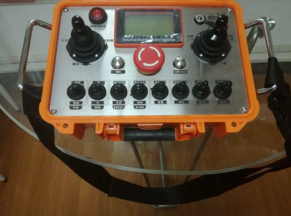
من الصعب المبالغة في تقدير الأهمية العملية للأنظمة الهيدروليكية في الصناعة الحديثة. فمعدات البناء، ومكابس التصنيع، والآلات الزراعية، وأسطح التحكم في الطيران للطائرات، ومعدات الرفع البحرية، وأنظمة الفرامل في السيارات، كلها تعتمد على أنظمة التحكم الهيدروليكية لتعمل. تجاوز حجم سوق المعدات الهيدروليكية العالمية 55 مليار دولار أمريكي في عام 2024، ولا يزال في تزايد مستمر، مدفوعًا بالمزايا التي لا غنى عنها التي توفرها الأنظمة الهيدروليكية: كثافة الطاقة العالية، والتحكم الدقيق في القوة، والقدرة على نقل قوى كبيرة عبر مسافات طويلة من خلال الخراطيم المرنة، والحماية المتأصلة من الحمل الزائد من خلال تخفيف الضغط.
لقد شاركنا في تصميم الأنظمة الهيدروليكية واستكشاف الأعطال وإصلاحها في العديد من فئات المعدات المختلفة، وهناك ملاحظة واحدة ثبتت صحتها باستمرار: إن أجهزة التحكم الهيدروليكية تكون دائمًا تقريبًا أكثر أهمية لأداء النظام من مكونات توليد الطاقة. فالمضخة القوية المقترنة بصمامات تحكم سيئة التصميم تنتج آلة تكون إما شديدة العدوانية بشكل خطير أو بطيئة بشكل محبط. أما إذا تم إقران المضخة نفسها بأجهزة تحكم نسبية مصممة هندسيًا بشكل جيد، فإن النتيجة تكون آلة يسهل التعامل معها، وتستجيب بشكل يمكن التنبؤ به، وتدوم لفترة أطول بكثير نظرًا لتقليل الأحمال الصدمية إلى أدنى حد.
إن فهم كيفية عمل أنظمة التحكم الهيدروليكية على المستوى الأساسي أمر مهم، ليس فقط للمهندسين الهيدروليكيين الذين يصممون أنظمة جديدة، بل أيضًا لفنيي الصيانة الذين يقومون بتشخيص المشكلات، ومتخصصي المشتريات الذين يقيّمون المعدات، ومديري المصانع الذين يسعون إلى فهم أسباب سلوك معداتهم على هذا النحو.
أين تُستخدم أجهزة التحكم الهيدروليكية
| الصناعة | نوع المعدات | وظيفة التحكم الهيدروليكي الأساسية |
|---|---|---|
| البناء | الحفارات، والرافعات، واللوادر | الاتجاه، السرعة، قوة ذراع الرافعة، الذراع، الجرافة |
| الزراعة | الجرارات، آلات الحصاد | نظام ربط ثلاثي النقاط، محور الدفع (PTO)، التحكم في الملحقات |
| التصنيع | المكابس، القولبة بالحقن | التحكم الدقيق في القوة والموضع |
| الفضاء الجوي | أسطح التحكم في الطيران | تحكم دقيق في الموقع، أنظمة أمان احتياطية |
| البحرية / البحرية البعيدة | الرافعات، المحركات الدافعة، أنظمة التوجيه | نقل القوة، التشغيل عن بُعد |
| السيارات | الكبح، التوجيه، ناقلات الحركة | استجابة سريعة، تحكم دقيق في الضغط |
| التعدين | المثاقب، الناقلات، مركبات LHD | قوة عالية، والتحكم عن بُعد والتحكم الذاتي |
| النفط والغاز | معدات رأس البئر، صمام منع الانفجار (BOP) | التحكم عن بُعد، التشغيل الآمن |
ما هو قانون باسكال وكيف يجعل التحكم الهيدروليكي ممكنًا؟
قانون باسكال هو المبدأ الفيزيائي الأساسي الذي يعتمد عليه عمل أنظمة التحكم الهيدروليكية. وقد صاغه بليز باسكال في عام 1653، وينص هذا القانون على أن الضغط المطبق على سائل محصور وغير قابل للانضغاط ينتقل دون انخفاض في جميع الاتجاهات عبر السائل بأكمله، ويؤثر بقوة متساوية على جميع المساحات المتساوية في الوعاء.
من الناحية الرياضية: P = F / A، حيث P هي الضغط بالباسكال (أو البار/psi)، وF هي القوة بالنيوتن (أو الرطل)، وA هي المساحة بالمتر المربع (أو البوصة المربعة) التي تُطبق عليها القوة.
تتضح الفعالية العملية لهذه العلاقة عند النظر إلى نظام يتألف من أسطوانتين متصلتين بخط سائل. إذا كانت مساحة مكبس الأسطوانة 1 تبلغ 1 سنتيمتر مربع ومساحة مكبس الأسطوانة 2 تبلغ 100 سنتيمتر مربع، فإن القوة البالغة 100 نيوتن المُطبقة على الأسطوانة 1 تولد ضغطًا يبلغ 100 نيوتن / 0.0001 م² = 1,000,000 باسكال (10 بار) في جميع أنحاء السائل. وينتج عن نفس الضغط البالغ 10 بار، عند تأثيره على مساحة مكبس الأسطوانة 2 البالغة 0.01 م²، قوة ناتجة تبلغ 10,000 نيوتن، وهو ما يمثل مضاعفة القوة بنسبة 100:1.
ولهذا السبب، يمكن للمشغل البشري الذي يمارس قوة متواضعة على عصا التحكم أو ذراع الصمام أن يتحكم في حفارة هيدروليكية تمارس قوى تُقاس بالطن. حيث تعمل الدائرة الهيدروليكية على تضخيم قوة الإدخال التحكمي بنسبة مساحة المشغل إلى مساحة الإدخال التحكمي، مع استخدام الضغط كوسيط مشترك لنقل الأمر عبر السائل.
تطبيق قانون باسكال على التحكم الهيدروليكي الفعلي
| المعلمة | قيمة مثال | الوحدة |
|---|---|---|
| ضغط خرج المضخة | 200-350 | حانة |
| التحكم في قوة الإدخال (عصا التحكم) | 5-20 | نيوتن |
| قطر تجويف الأسطوانة (ذراع حفارة نموذجي) | 100-150 | مم |
| قوة الخرطوم عند 250 بار | 196-442 | كيلو نيوتن |
| معامل مضاعفة القوة | ~10,000:1 | النسبة |
إلى جانب مضاعفة القوة، يفسر قانون باسكال أيضًا السبب الذي يجعل الأنظمة الهيدروليكية قادرةً على نقل الطاقة عبر خراطيم مرنة تمتد حول الزوايا، وعبر المساحات الضيقة، وعبر مسافات كبيرة دون الحاجة إلى وصلات ميكانيكية. فالضغط ينتقل عبر السائل بشكل متساوٍ بغض النظر عن المسار الذي تسلكه الخرطوم، مما يمنح الأنظمة الهيدروليكية ميزة هائلة من حيث مرونة التصميم مقارنةً بأنظمة النقل الميكانيكية.
هناك نقطة دقيقة يغفلها العديد من الشروحات التمهيدية: السوائل الهيدروليكية الحقيقية ليست غير قابلة للانضغاط تمامًا. فعند الضغوط العالية جدًّا، ينضغط الزيت بشكل قابل للقياس (يبلغ معامل الانضغاط الحجمي للزيت المعدني النموذجي حوالي 1.7 جيجا باسكال، ما يعني انضغاطًا حجميًّا قدره 1% لكل 170 بار من الضغط). ولهذه القابلية للانضغاط آثار مهمة على استجابة التحكم الهيدروليكي، لأن عمود السائل بين صمام التحكم والمشغل يعمل كزنبرك. وفي حالات الخراطيم الطويلة أو الدوائر ذات الحجم الكبير، يتسبب تأثير الزنبرك الهيدروليكي هذا في حدوث تأخر في التحكم وقد يؤدي إلى عدم الاستقرار في أنظمة التحكم في الموضع ذات الحلقة المغلقة.
ما هي المكونات الرئيسية لنظام التحكم الهيدروليكي؟
لا يُعد نظام التحكم الهيدروليكي جهازًا واحدًا، بل هو مجموعة متكاملة من المكونات، يؤدي كل منها وظيفة محددة ضمن سلسلة نقل الطاقة والتحكم الشاملة. ومن الضروري فهم دور كل مكون قبل دراسة كيفية عمل أنواع أنظمة التحكم المختلفة.
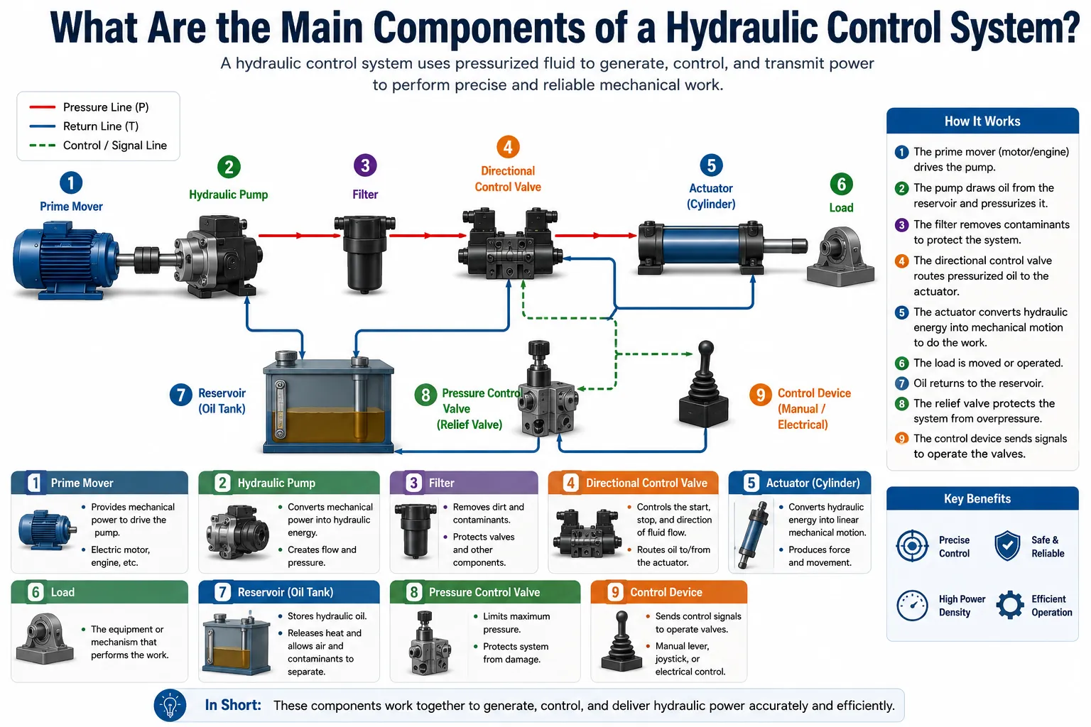
المضخة الهيدروليكية
تقوم المضخة بتحويل الطاقة الميكانيكية (الواردة من محرك كهربائي أو محرك ديزل أو عمود نقل الطاقة) إلى طاقة هيدروليكية عن طريق توليد التدفق. لا تولد المضخة الضغط بشكل مباشر؛ بل تولد التدفق، ويحدث الضغط نتيجة للمقاومة التي يواجهها هذا التدفق في اتجاه مجرى التدفق. هذا التمييز مهم عند استكشاف أعطال النظام: فالنظام الذي لا يوجد فيه ضغط عادةً ما يكون إما أن المضخة فيه لا تولد تدفقًا، أو أن صمام التنفيس يفرغ كل التدفق إلى الخزان قبل أن يتسنى للضغط أن يتراكم.
تشمل أنواع المضخات الشائعة في أنظمة التحكم الهيدروليكية المضخات التروسية (ذات السعة الثابتة، البسيطة، المستخدمة في التطبيقات ذات الضغط المنخفض إلى المتوسط)، ومضخات الريشة (ذات السعة الثابتة أو المتغيرة، وأكثر هدوءًا من مضخات التروس، وتُستخدم في التطبيقات الصناعية)، ومضخات المكبس (ذات السعة المتغيرة أو الثابتة، وقادرة على تحمل ضغط عالٍ يصل إلى 450+ بار، وهي الخيار السائد للمعدات المتنقلة والأنظمة الصناعية عالية الأداء).
تُعد المضخات المكبسية ذات السعة المتغيرة ذات أهمية خاصة في التحكم الهيدروليكي لأنها تقوم بضبط تدفقها الناتج استجابةً لاحتياجات النظام، إما من خلال التحكم المعوض بالضغط (تقليل السعة للحفاظ على ضغط أقصى محدد) أو التحكم المستشعر للحمل (ضبط السعة للحفاظ على هامش ضغط ثابت أعلى من ضغط الحمل). وهذه القدرة على تغيير السعة هي ما يتيح للأنظمة الهيدروليكية الحديثة أن تكون عالية الكفاءة في استخدام الطاقة، بدلاً من تداول تدفق المضخة الكامل باستمرار عبر صمام التنفيس.
المحركات الهيدروليكية
تقوم المشغلات بتحويل الطاقة الهيدروليكية مرة أخرى إلى طاقة ميكانيكية لأداء عمل مفيد. وتقوم المشغلات الخطية (الأسطوانات) بتحويل ضغط السائل إلى قوة دفع أو سحب خطية. أما المشغلات الدوارة (المحركات الهيدروليكية، والمشغلات الدوارة) فتقوم بتحويل تدفق السائل إلى عزم دوران وسرعة.
تساوي قوة الخرج الناتجة عن الأسطوانة الضغط مضروبًا في مساحة المكبس. وتساوي سرعة الأسطوانة معدل التدفق مقسومًا على مساحة المكبس. وتحدد هاتان المعادلتان سلوك الأسطوانة بشكل كامل، وتشكلان نقطة الانطلاق لأي حساب لتحديد أبعاد المشغل.
عزم الدوران الناتج عن المحرك يساوي الضغط مضروبًا في سعة المحرك مقسومًا على 2π. وسرعة المحرك تساوي معدل التدفق مقسومًا على سعة المحرك. وتحدد هذه العلاقات أيضًا أداء المشغل الدوار.
السائل الهيدروليكي
يُعد السائل وسيلة نقل الطاقة ومواد التشحيم لجميع الأجزاء المتحركة داخل النظام. ويؤثر اختيار السائل الهيدروليكي على توافق الموانع التسرب، واللزوجة عند درجة حرارة التشغيل، ومقاومة الأكسدة، وحساسية المكونات الدقيقة للتلوث. وتُعد السوائل الهيدروليكية القائمة على الزيوت المعدنية هي الأكثر شيوعًا. وتُستخدم السوائل المكونة من الماء والجليكول وإسترات الفوسفات في الحالات التي تتطلب مقاومة للحريق. أما السوائل القابلة للتحلل البيولوجي فتُستخدم في التطبيقات التي تراعي البيئة.
يمكن القول إن نظافة السوائل هي العامل الأهم على الإطلاق في إطالة عمر أنظمة التحكم الهيدروليكية. تعتبر الصمامات النسبية والصمامات المؤازرة التي تبلغ فجوات بكراتها ما بين 5 و25 ميكرومتر حساسة للغاية تجاه تلوث الجسيمات. ويحدد معيار النظافة ISO 4406 تركيز الجسيمات التي يزيد حجمها عن 4 و6 و14 ميكرومتر لكل ملليلتر. وعادةً ما يشترط مصنعو الصمامات التناسبية الامتثال لمعيار ISO 4406 من الفئة 17/15/12 أو أعلى؛ بينما تتطلب الصمامات المؤازرة الفئة 15/13/10 أو أعلى.
معدات الخزانات والمعالجة
يقوم الخزان بتخزين السائل، ويسمح بتبديد الهواء والحرارة المحبوسين فيه، ويوفر حجمًا للترسيب حيث تغرق الشوائب الخشنة قبل إعادة تدوير الزيت. تعمل المبادلات الحرارية (المبردات) على الحفاظ على درجة حرارة السائل ضمن نطاق اللزوجة المطلوب لضمان الأداء السليم لصمامات التحكم. تعمل المرشحات على إزالة الشوائب من السائل، حيث تعمل مرشحات الشفط على حماية المضخة وخط العودة، بينما تعمل مرشحات الضغط على حماية صمامات التحكم الدقيقة.
ملخص مكونات النظام الرئيسية
| المكون | الوظيفة | المعلمة الرئيسية |
|---|---|---|
| المضخة الهيدروليكية | يحول الطاقة الميكانيكية إلى طاقة هيدروليكية | السعة، الضغط الأقصى، الكفاءة |
| صمام التحكم في الاتجاه | تتدفق المسارات إلى منفذ المشغل الصحيح | معدل التدفق، نوع الصمام، طريقة التشغيل |
| صمام التحكم في الضغط | يحد من ضغط الدائرة أو ينظمه | ضغط التكسير، نطاق التصلب |
| صمام التحكم في التدفق | ينظم سرعة المشغل | معدل التدفق، تعويض الضغط |
| صمام فحص | يُسمح بالسير في اتجاه واحد فقط | ضغط التصدع، معدل التسرب |
| الأسطوانة الهيدروليكية | يحول الضغط إلى قوة خطية | قطر الأسطوانة، شوط المكبس، الضغط المقنن |
| المحرك الهيدروليكي | يحول التدفق إلى عزم دوران | السعة، معدل الضغط، الكفاءة |
| خزان | تخزين السوائل ومعالجتها | السعة، الحواجز، الترشيح |
| تصفية | يزيل التلوث | تصنيف الميكرون، ونسبة بيتا، وإعدادات التجاوز |
| المبادل الحراري | يتحكم في درجة حرارة السائل | قدرة التبريد، انخفاض الضغط |
| المركم | يخزن الطاقة الهيدروليكية | ضغط الشحن المسبق، الحجم، النوع |
كيف تعمل الأنواع المختلفة من أنظمة التحكم الهيدروليكية؟
تُصنف أنظمة التحكم الهيدروليكية وفقًا للطريقة التي تنظم بها الطاقة الهيدروليكية، وكيفية استجابتها لظروف الأحمال المتغيرة، وما إذا كانت تستخدم التغذية الراجعة ذات الحلقة المفتوحة أو المغلقة. ويتميز كل نوع من هذه الأنظمة بخصائص أداء ومستويات كفاءة وملاءمة للتطبيقات متميزة.
الأنظمة الهيدروليكية ذات المركز المفتوح
في نظام المركز المفتوح، وعندما لا يتم تشغيل أي وظيفة، يدور إجمالي خرج المضخة بضغط منخفض عبر الممر المركزي لصمامات التحكم الاتجاهي ويعود إلى الخزان. وعندما يقوم المشغل بتحويل صمام اتجاهي، يتم سد مسار المركز المفتوح ويتم توجيه الزيت إلى المشغل. تستمر المضخة في الضخ بمعدل تدفق ثابت بغض النظر عما إذا كان العمل قيد التنفيذ أم لا.
تتميز الأنظمة ذات المركز المفتوح بالبساطة وانخفاض التكلفة والمتانة. وهي الخيار التقليدي للجرارات الزراعية والمعدات الصناعية القديمة، والتطبيقات التي لا تتطلب أداء وظائف متعددة في آن واحد. ويكمن القيد الرئيسي لهذه الأنظمة في عدم كفاءتها في استهلاك الطاقة: حيث تستهلك المضخة الطاقة باستمرار حتى خلال فترات التوقف دون حمل، لأنها تضطر إلى دفع التدفق الكامل عبر الممر المركزي في مواجهة انخفاض الضغط في مسار العودة.
الأنظمة الهيدروليكية ذات المركز المغلق
في الأنظمة ذات المركز المغلق، تعمل صمامات التحكم الاتجاهي على سد جميع المنافذ عندما تكون في الوضع المحايد. ولا يتدفق الزيت عبر الصمام عند عدم إصدار أمر بأي وظيفة. وهذا يتطلب إما مضخة ذات سعة متغيرة (تقلل من إنتاجها إلى ما يقارب الصفر عندما تكون الصمامات في الوضع المركزي) أو مضخة ذات سعة ثابتة مقترنة بمخزن ضغط عالي وصمام تفريغ يقوم بتصريف تدفق المضخة إلى خزان الضغط المنخفض عندما يكون المخزن مشحونًا بالكامل.
تتميز الأنظمة ذات المركز المغلق بكفاءة أكبر في استهلاك الطاقة مقارنةً بالأنظمة ذات المركز المفتوح خلال فترات التوقف عن العمل، وهي تُعد ميزة قياسية في المعدات المتنقلة الحديثة التي تُعطى فيها الأولوية لتوفير الوقود. كما أنها تتيح دمج وظائف متعددة بسهولة أكبر دون حدوث تعارضات في توزيع التدفق.
أنظمة التحكم المستشعرة للحمل
تمثل أنظمة استشعار الحمل (LS) أحدث ما توصلت إليه التكنولوجيا في مجال كفاءة التحكم الهيدروليكي في المركبات. يقوم النظام بقياس أعلى ضغط للحمل الموجود في أي وظيفة نشطة بشكل مستمر من خلال شبكة صمامات التبديل، ويقوم بإرسال إشارة ضغط استشعار الحمل هذه إلى وحدة التحكم في سعة المضخة. وتقوم المضخة بضبط سعتها للحفاظ على فرق ضغط ثابت أعلى من ضغط الحمل، وعادةً ما يكون هذا الفرق في حدود 15-25 بار فوق أعلى مستوى للحمل.
والنتيجة العملية لذلك هي أن المضخة توفر فقط التدفق الذي تحتاجه الوظائف النشطة فعليًّا، عند ضغط لا يتجاوز إلا قليلاً ما تتطلبه الأحمال. وهذا يتجنب كلاً من هدر التدفق الذي يحدث في الأنظمة ذات المركز المفتوح (حيث يتم تدوير التدفق الزائد) وهدر الضغط الذي يحدث في الأنظمة التي تعمل بأقصى ضغط بغض النظر عن الحمل. تُعد أنظمة استشعار الحمل هي البنية السائدة في الحفارات الحديثة واللوادر ذات العجلات والمعدات الزراعية.
أنظمة الضغط الثابت (المُعوضة ضغطياً)
في أنظمة الضغط الثابت، تحافظ المضخة على ضغط خرج ثابت بغض النظر عن الطلب على التدفق. أما مضخات المكبس ذات السعة المتغيرة والمزودة بوحدات تحكم لتعويض الضغط، فتقوم بتقليل سعتها كلما اقترب ضغط الحمل من الحد الأقصى المحدد، مما يحافظ على ضغط ثابت بشكل أساسي بينما يتراوح التدفق من الصفر إلى السعة القصوى للمضخة.
تُستخدم أنظمة الضغط الثابت بشكل شائع في الآلات الصناعية، والقولبة بالحقن، والتطبيقات التي تتطلب استجابة سريعة لتغيرات الطلب على التدفق، لأن الضغط يكون متاحًا دائمًا عند الصمام دون أي تأخير في التراكم.
مقارنة أنواع الأنظمة
| نوع النظام | كفاءة الطاقة | سرعة الاستجابة | متعدد الوظائف | التعقيد | التطبيقات النموذجية |
|---|---|---|---|---|---|
| مضخة ثابتة ذات مركز مفتوح | منخفض | متوسط | محدود | منخفض | الجرارات القديمة، والمعدات البسيطة |
| مضخة ثابتة ذات مركز مغلق + مخزن ضغط | متوسط | سريع (المركم) | جيد | متوسط | الصناعية، المطابع |
| مضخة متغيرة ذات مركز مغلق | مرتفع | متوسط-سريع | جيد | متوسط | المعدات المتنقلة الحديثة |
| مضخة متغيرة تستشعر الحمل | مرتفع جدًّا | سريع | ممتاز | مرتفع | الحفارات، واللوادر، والرافعات |
| مضخة متغيرة ذات ضغط ثابت | مرتفع | سريع جدًا | جيد | متوسط-مرتفع | الصناعة، القولبة بالحقن |
| كهربائي-هيدروليكي (مُسيَّر) | مرتفع جدًّا | سريع جدًا | ممتاز | مرتفع جدًّا | الفضاء، صناعة الدقة |
ما هي أنواع صمامات التحكم الهيدروليكية المستخدمة وكيف تعمل؟
تُعد الصمامات عناصر التحكم الفعالة في أي نظام هيدروليكي. فهي تحدد مسار السائل، والضغط الذي يتدفق به، ومعدل تدفقه. ويُعد فهم وظيفة وتصميم كل فئة من فئات الصمامات أمرًا أساسيًّا لفهم كيفية عمل أنظمة التحكم الهيدروليكية.
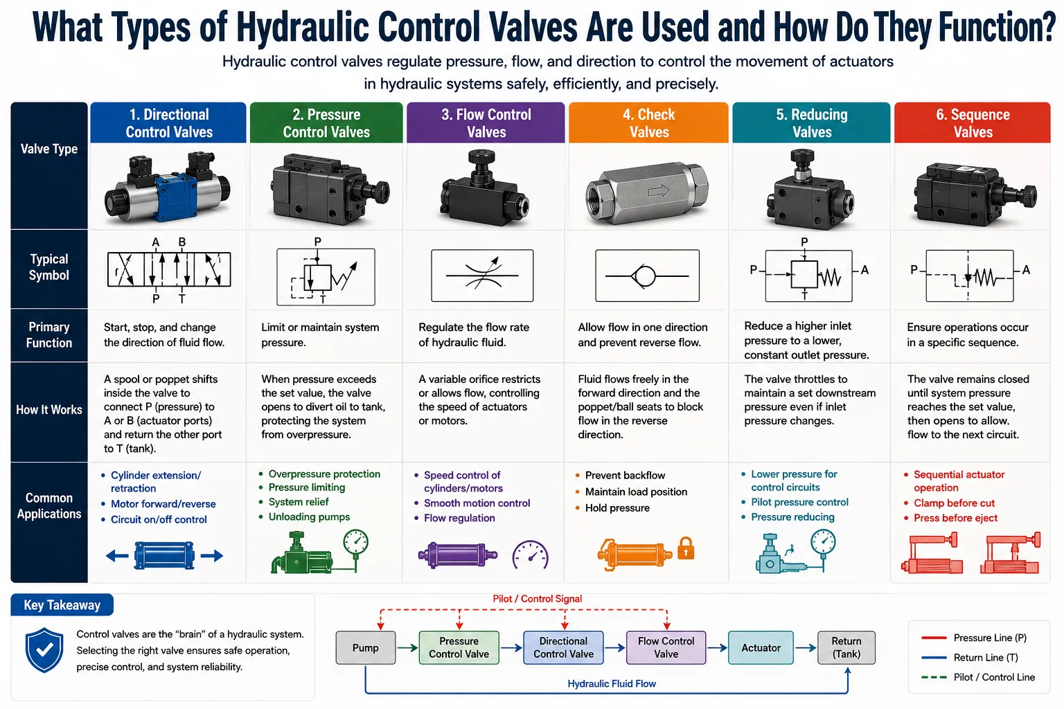
صمامات التحكم في الاتجاه
تقوم صمامات التحكم الاتجاهي (DCVs) بتوجيه السائل من المضخة إلى منفذ المشغل المناسب، وإعادة السائل من منفذ المشغل المقابل إلى الخزان. ويتم وصفها بعدد أوضاع التشغيل وعدد المنافذ: فالصمام 4/3 يحتوي على 4 منافذ (P – ضغط الدخول، T – الخزان، A – منفذ المشغل 1، B – منفذ المشغل 2) و3 أوضاع (التحويل إلى A، الوضع المحايد، التحويل إلى B).
الكرس هو العنصر الأسطواني المنزلق داخل جسم الصمام، والذي يحدد مسار التدفق من خلال موضعه. في الوضع المحايد، تعمل حواف البكرة على سد المنافذ أو ربطها حسب نوع البكرة المحايدة (مركز مفتوح، مركز مغلق، مركز ترادفي، مركز عائم). وعندما تتحرك البكرة، تنفتح حواف القياس لربط P بـ A (و B بـ T) أو P بـ B (و A بـ T).
تشمل طرق التشغيل: التشغيل اليدوي (بواسطة ذراع أو زر)، والتشغيل الميكانيكي (بواسطة كامة أو مزلاج)، والتشغيل الهيدروليكي التوجيهي (حيث يؤدي ضغط توجيهي صغير إلى تحريك المكبس الرئيسي)، والتشغيل بالملف اللولبي (حيث يقوم الملف الكهرومغناطيسي بتحريك المكبس مباشرةً أو عبر مرحلة توجيهية)، والتشغيل بالملف اللولبي النسبي (حيث ينتج التيار المتغير تحريكًا متغيرًا للمكبس من أجل التحكم النسبي).
صمامات التحكم في الضغط
صمامات التنفيس: يتم ضبط الحد الأقصى لضغط الدائرة عن طريق فتح الصمام لتحويل التدفق إلى الخزان عندما يصل الضغط إلى مستوى الضغط المحدد للتنفيس. وتُعد هذه الصمامات جهاز الحماية الأساسي من الحمل الزائد في أي دائرة هيدروليكية. يجب أن تحتوي كل دائرة هيدروليكية على صمام تنفيس واحد على الأقل. تستجيب صمامات التنفيس ذات التأثير المباشر بسرعة، لكنها تتميز بفارق ضغط أعلى (الفرق بين ضغط الانفتاح وضغط التدفق الكامل). أما صمامات التنفيس التي تعمل بتشغيل تجريبي، فهي تتميز بتنظيم أكثر دقة للضغط مع فارق ضغط أقل، مما يجعلها مناسبة للتحكم الدقيق في الضغط.
صمامات تخفيض الضغط: يُقيد الضغط الأقصى في الدائرة الفرعية بقيمة أقل من ضغط الدائرة الرئيسية. وعلى عكس صمامات التنفيس (التي تكون مغلقة عادةً)، فإن صمامات التخفيض تكون مفتوحة عادةً وتُغلق للحد من الضغط في اتجاه مجرى التدفق. وتُستخدم في الدوائر التوجيهية، ودوائر التثبيت، وأي دائرة فرعية تتطلب ضغطًا أقصى أقل من ضغط النظام.
صمامات التسلسل: لا يُسمح بتدفق التيار إلى الدائرة الثانوية إلا بعد وصول ضغط الدائرة الأولية إلى القيمة المحددة للصمام، مما يضمن اتباع تسلسل محدد للعمليات.
صمامات التوازن: تمنع انطلاق المشغل بشكل غير متحكم فيه عندما يحاول الحمل المعلق دفع المشغل بسرعة تفوق قدرة المضخة على توفير التدفق. وهي تحافظ على ضغط عكسي على منفذ العودة الخاص بالمشغل، مما يتطلب إشارة توجيهية إيجابية من جانب الإمداد لفتحها. وهي ضرورية في الرافعات، والمكابس، وأي تطبيقات للأسطوانات التي تتحمل أحمالاً رأسية.
صمامات التفريغ: تضخ مضخة التفريغ السائل إلى الخزان عند ضغط منخفض عندما يصل ضغط النظام (الذي يأتي عادةً من المركم) إلى مستوى محدد. تُستخدم في دوائر المركم للسماح للمضخة بالعمل في وضع الخمول باستهلاك منخفض للطاقة، بينما يقوم المركم بتلبية الطلب.
صمامات التحكم في التدفق
فتحة ثابتة: قيد دائم يؤدي إلى انخفاض في الضغط يتناسب مع مربع معدل التدفق. وهو بسيط ولكنه لا يأخذ في الحسبان تقلبات الضغط.
صمامات الإبرة (فتحة قابلة للتعديل): مانع تدفق قابل للضبط يدويًّا. إنه غير مكلف وبسيط، لكنه غير مزود بنظام تعويض الضغط، مما يعني أن التدفق يتغير مع تغيرات ضغط الحمل.
صمامات التحكم في التدفق المعوضة للضغط: الحفاظ على معدل تدفق ثابت بغض النظر عن تقلبات الضغط في اتجاه التيار أو عكسه، وذلك باستخدام معوض ضغط داخلي يحافظ على فرق ضغط ثابت عبر فتحة القياس. ويُعد ذلك أمرًا ضروريًا عندما تكون سرعة المشغل الثابتة مطلوبة في ظل ظروف تحميل متفاوتة.
صمامات الأولوية: تأكد من أن الدائرة الحيوية (مثل نظام التوجيه) تتلقى دائمًا التدفق المطلوب لها قبل توفير أي تدفق متبقي للدوائر الثانوية (مثل وظائف التشغيل).
صمامات الفحص
تسمح الصمامات الفحصية بالتدفق في اتجاه واحد فقط وتمنع التدفق العكسي. وهي تحمي المضخات من التدفق العكسي أثناء ضغط النظام، وتحافظ على موضع المشغل عندما يكون الصمام الاتجاهي في الوضع المحايد (تثبيت الحمل)، وتوجه التدفق في دوائر شحن المركم. تضيف الصمامات الفحصية التي تعمل بإشارة توجيهية القدرة على فتح الاتجاه الذي يكون مغلقًا عادةً عند تطبيق إشارة توجيهية، وتُستخدم في تطبيقات تثبيت الحمل التي تتطلب خفضًا متحكمًا فيه.
جدول ملخص وظائف الصمامات
| نوع الصمام | عادةً | الوظيفة | التطبيق الرئيسي |
|---|---|---|---|
| صمام التنفيس | مغلق | يحدد الحد الأقصى للضغط | حماية الدائرة من الحمل الزائد |
| صمام تخفيض الضغط | فتح | يحدد الحد الأقصى للضغط في الفرع | الدوائر التجريبية، التثبيت |
| صمام التسلسل | مغلق | يفرض ترتيب العمليات | اضغط، ثم ثبت، ثم حرك للأمام |
| صمام التوازن | مغلق | يمنع الانفلات الناتج عن الحمل | الرافعات، الأسطوانات الرأسية |
| صمام التفريغ | فتح | تقوم المضخة بتفريغ الحمولة عند الضغط المنخفض | دوائر المركم |
| صمام التحكم في الاتجاه | محجوب (ذو مركز مغلق) | اتجاه تدفق المسارات | التحكم الكامل في المشغلات |
| صمام الإبرة | متغير | يضبط معدل التدفق يدويًّا | تعديل السرعة |
| التحكم في التدفق المقاوم للضغط | متغير | يحافظ على تدفق ثابت | التحكم المستمر في السرعة |
| صمام فحص | مغلق | يمنع التدفق العكسي | حماية الدوائر الكهربائية |
| صمام فحص يعمل بتحكم يدوي | مغلق (قابل للاحتفاظ به) | تثبيت الحمل مع التحرير | خطافات الرافعات، المكابس |
| صمام الأولوية | مفتوح للأولوية | يضمن تدفق التيار في الدوائر الحيوية | أولوية التوجيه |
كيف يختلف التحكم في الضغط الهيدروليكي عن التحكم في التدفق؟
يُعد هذا التمييز من أهم التمييزات من الناحية النظرية في الأنظمة الهيدروليكية، وهو ما يربك الكثير من المبتدئين في مجال الهندسة الهيدروليكية. فالضغط والتدفق موجودان في كل دائرة هيدروليكية، لكنهما يؤديان وظائف تحكم مختلفة جوهريًا.
الضغط هو الذي يحدد القوة. تساوي القوة الناتجة عن الأسطوانة الهيدروليكية ضغط النظام مضروبًا في مساحة المكبس. إذا كنت ترغب في التحكم في قوة دفع المكبس، أو قوة إمساك المشبك، أو الحمولة التي يمكن للرافعة رفعها، فإنك تتحكم في الضغط. ويتم التحكم في الضغط من خلال صمامات التنفيس (التي تحد من الضغط الأقصى)، وصمامات خفض الضغط (التي تحد من ضغط الدائرة الفرعية)، وأجهزة التحكم المتغيرة في تعويض ضغط المضخة.
التدفق هو الذي يحدد السرعة. تساوي سرعة الأسطوانة الهيدروليكية معدل التدفق الحجمي الداخل إلى الأسطوانة مقسومًا على مساحة المكبس. إذا أردت التحكم في سرعة تمدد الأسطوانة أو سرعة دوران المحرك، فعليك التحكم في معدل التدفق. يتم التحكم في التدفق من خلال الصمامات الاتجاهية النسبية (التي تقيس التدفق عن طريق تغيير مساحة فتحة البكرة)، وصمامات التحكم في التدفق، والتحكم المتغير في تدفق المضخة.
من الأخطاء الشائعة في تصميم الأنظمة الهيدروليكية محاولة التحكم في القوة عن طريق تقييد التدفق، أو محاولة التحكم في السرعة عن طريق ضبط الضغط. ولا يعمل أي منهما بشكل صحيح. فالتقييد التدفق يقلل السرعة ولكنه لا يحد من القوة القصوى التي يمكن للمشغل توليدها (والتي لا تزال تتحدد وفقًا لإعداد صمام التنفيس). أما ضبط الضغط فيغير القوة القصوى المتاحة ولكنه لا يتحكم في السرعة بشكل مباشر.
علاقة القوة
تساوي الطاقة الهيدروليكية الضغط مضروبًا في معدل التدفق: P_power = p × Q. توضح هذه العلاقة أن النظام يمكنه توفير نفس الطاقة عند الضغط العالي والتدفق المنخفض، أو عند الضغط المنخفض والتدفق العالي. في تصميم الأنظمة الموفرة للطاقة، يتمثل الهدف في تزويد المشغل بالضغط ومعدل التدفق اللذين يحتاجهما بالضبط عند نقطة الحمل، دون ضغط زائد (يتم التحكم فيه بواسطة مضخات تعويض الضغط) ودون تدفق زائد (يتم التحكم فيه بواسطة أنظمة الإزاحة المتغيرة أو أنظمة استشعار الحمل).
مقارنة بين التحكم في الضغط والتحكم في التدفق
| معلمة التحكم | عناصر التحكم | نوع الصمام المستخدم | تأثير المخرجات |
|---|---|---|---|
| الضغط | القوة / عزم الدوران | التخفيف، والتقليل، والتعويض | مدى قوة الدفع التي يولدها المشغل |
| التدفق | السرعة | التحكم في التدفق، صمام تيار مستمر نسبي (DCV) | مدى سرعة حركة المشغل |
| كلاهما (نسبي) | القوة والسرعة | مضخة DCV + LS متناسبة | قوة وسرعة قابلتان للتعديل بشكل كامل |
ما هو دور المضخات والمشغلات في دوائر التحكم الهيدروليكية؟
تحدد المضخة والمشغل نطاق الطاقة الذي يعمل ضمنه نظام التحكم. ولا يمكن لصمامات التحكم سوى تعديل الطاقة التي أنتجتها المضخة بالفعل؛ فهي لا تستطيع توليد طاقة أو توفير طاقة لا تستطيع المضخة توفيرها.
المضخات ذات السعة المتغيرة والتحكم في النظام
تُعد المضخات ذات المكابس المحورية ذات السعة المتغيرة حجر الزاوية في الأنظمة الهيدروليكية الحديثة القابلة للتحكم. تستخدم هذه المضخات صفيحة مائلة تحدد زاويتها طول شوط المكابس، وبالتالي سعة المضخة لكل دورة. ويؤدي تدوير الصفيحة المائلة من الزاوية القصوى إلى الزاوية الدنيا إلى تقليل السعة من الحد الأقصى إلى ما يقارب الصفر، بشكل مستمر ونسبي.
يتم التحكم في زاوية لوحة التأرجح بواسطة مكبس مؤازر يستجيب لإشارات التحكم الصادرة عن معوضات الضغط، أو منظمات استشعار الحمل، أو وحدات التحكم الإلكترونية. وهذا يعني أنه يمكن توجيه المضخة لإنتاج أي تدفق يتراوح من الصفر إلى الحد الأقصى، عند أي ضغط يصل إلى مستوى الضغط المحدد للتنفيس، بحيث يتناسب إنتاجها بدقة مع احتياجات النظام.
يُعد التحكم الإلكتروني في المضخة — حيث يتم التحكم في موضع الصفيحة المائلة بواسطة وحدة تحكم إلكترونية عبر صمام نسبي مركب على مكبس المؤازرة — أحدث ما توصلت إليه التكنولوجيا في مجال كفاءة ودقة الأنظمة الهيدروليكية. فهو يتيح للمضخة توقع التغيرات في الطلب بناءً على مدخلات المشغل بدلاً من الاستجابة فقط بعد انحراف الضغط أو التدفق عن القيمة المستهدفة، مما يقلل من تأخر الاستجابة المتأصل في التحكم الهيدروميكانيكي البحت.
تحديد حجم المشغل وجودة التحكم
يؤثر حجم المشغل بشكل مباشر على جودة التحكم. فالمشغلات ذات الحجم الأصغر من المطلوب (الأسطوانات ذات القطر الصغير أو المحركات ذات الإزاحة المنخفضة) تعمل تحت ضغط عالٍ لتوليد القوة المطلوبة، مما يترك هامش ضغط ضئيلًا لصمامات التحكم لتعديله. أما المشغلات ذات الحجم الأكبر من المطلوب، فتعمل تحت ضغط منخفض لتوليد القوة المطلوبة، لكنها تتطلب معدلات تدفق كبيرة لتحقيق السرعة المطلوبة، مما يستلزم سعة مضخة عالية.
يعمل المشغل المثالي للتطبيقات القابلة للتحكم عند ضغط نظام أقصى يتراوح بين 40 و70% في ظل أحمال العمل العادية. ويوفر نطاق الضغط هذا هامشًا كافيًا للتحكم النسبي بالصمام دون حدوث خسائر مفرطة ناتجة عن الخانق، مع الحفاظ في الوقت نفسه على صلابة تحميل كافية لمقاومة الاضطرابات الخارجية.
وظيفة المركم في دوائر التحكم
تقوم المراكم الهيدروليكية بتخزين طاقة السائل المضغوط وإطلاقها عند الحاجة. من ناحية أنظمة التحكم، تؤدي المراكم ثلاث وظائف: فهي تلبي الطلب الفوري على ذروة التدفق الذي يتجاوز سعة المضخة (مما يقلل من متطلبات حجم المضخة)، وتمتص نبضات الضغط الصادرة عن المضخات المكبسية (مما يحسن جودة إشارة التحكم)، وتحافظ على ضغط النظام أثناء فترات توقف المضخة القصيرة (مما يتيح تنفيذ تسلسلات إيقاف التشغيل الآمنة).
تتميز كل من مخازن الضغط المثانية، ومخازن الضغط المكبسية، ومخازن الضغط الحاجزية بخصائص أداء محددة فيما يتعلق بسرعة الاستجابة، ونسبة حجم الغاز، ومتطلبات الصيانة.
كيف تعمل أنظمة التحكم الكهروهيدروليكية والتناسبية؟
يمثل التحكم الكهروهيدروليكي دمج الذكاء الذي يتميز به التحكم الإلكتروني مع الطاقة الهيدروليكية. ويوفر هذا المزيج قدرات لا يمكن تحقيقها لا بالإلكترونيات وحدها ولا بالهيدروليكا وحدها: فقدرة المعالجة والدقة التي تتميز بها الإلكترونيات، إلى جانب الكثافة العالية للطاقة ومضاعفة القوة التي تتميز بها الهيدروليكا.
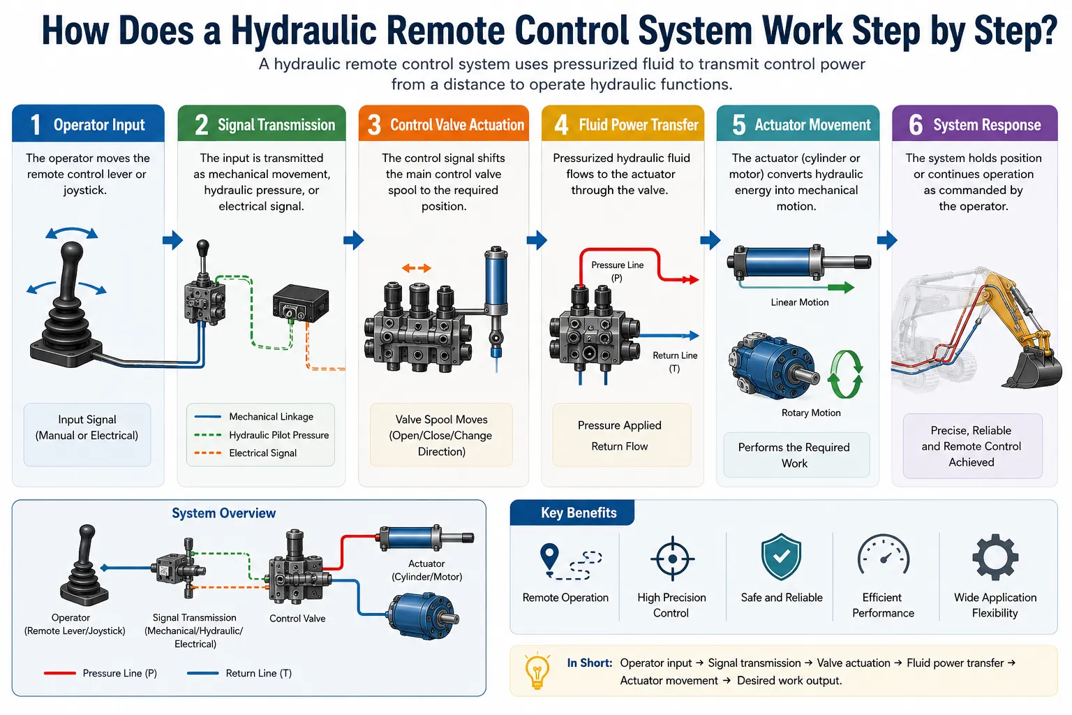
تشغيل الصمام النسبي
يعمل الصمام اللولبي النسبي وفقًا لمبدأ أن القوة المغناطيسية التي ينتجها الملف اللولبي تتناسب مع التيار المتدفق عبره. وعندما يزداد التيار، تزداد القوة المغناطيسية المؤثرة على حديد الصمام بشكل متناسب، مما يؤدي إلى تحريك عمود الصمام بمقدار مماثل عكس اتجاه زنبرك التمركز.
يكمن الابتكار الرئيسي للصمامات النسبية مقارنةً بالصمامات الكهرومغناطيسية البسيطة التي تعمل بنظام التشغيل/الإيقاف في هذه العلاقة المستمرة بين التيار والقوة. ومن خلال التحكم الدقيق في تيار الملف الكهرومغناطيسي (الذي يتراوح عادةً بين 0 و2 أمبير)، يمكن ضبط موضع المكبس على أي قيمة وسيطة، مما ينتج عنه معدل تدفق أي قيمة بين الصفر والحد الأقصى.
توفر إلكترونيات مكبر التيار النسبي التحكم الدقيق في التيار. فهي تستقبل إشارة تحكم منخفضة المستوى (من عصا التحكم، أو المخرج التناظري لوحدة التحكم المنطقية القابلة للبرمجة (PLC)، أو جهاز استقبال لاسلكي)، وتطبق وظائف التسارع القابلة للبرمجة وإعدادات الكسب، وتولد تيار الملف اللولبي النسبي باستخدام مرحلة خرج PWM (تعديل عرض النبضة). وتعمل إشارة التذبذب، وهي تذبذب صغير عالي التردد يُضاف إلى تيار الأوامر، على إبقاء الملف في حركة دقيقة مستمرة للتغلب على الاحتكاك الساكن وتحسين أداء عتبة التشغيل.
التحكم الكهروهيدروليكي ذو الحلقة المغلقة
يُعد التحكم الكهروهيدروليكي ذو الحلقة المفتوحة (إرسال أمر، وافتراض أن المشغل يستجيب له) كافياً للعديد من التطبيقات، لكنه لا يستطيع التعويض عن اضطرابات الحمل، أو تغيرات درجة حرارة السائل، أو تآكل الصمام. يضيف التحكم ذو الحلقة المغلقة مستشعر تغذية مرتدة (محول موضع، أو محول ضغط، أو مستشعر سرعة) ووحدة تحكم تقارن باستمرار الناتج الفعلي بقيمة الضبط المطلوبة، وتقوم بضبط إشارة الصمام لإزالة أي خطأ.
تحقق أنظمة الصمامات المؤازرة المزودة بنظام ردود فعل لموضع المكبس باستخدام مستشعر LVDT دقة في التحكم في الموضع تبلغ ±0.1 مم أو أفضل. ويمكن لأنظمة التحكم في المكابس الكهروهيدروليكية المزودة بنظام ردود فعل للقوة الحفاظ على قوة الضغط في نطاق ±0.5% من القيمة المحددة على طول الشوط الكامل. ولا يمكن تحقيق مستويات الأداء هذه باستخدام التحكم الهيدروليكي ذي الحلقة المفتوحة.
تكامل أجهزة التحكم المنطقية القابلة للبرمجة (PLC) والكمبيوتر
تقوم الأنظمة الهيدروليكية الحديثة في بيئات التصنيع بربط الصمامات النسبية والصمامات المؤازرة بوحدات التحكم المنطقية القابلة للبرمجة (PLC) عبر مخرجات تناظرية (4-20 مللي أمبير أو 0-10 فولت) أو بروتوكولات شبكات الحقل الرقمية (Profibus، Profinet، EtherCAT، CANopen). ويتيح هذا التكامل ما يلي:
- أنماط حركة قابلة للبرمجة مع تسارع وتباطؤ يمكن التحكم فيهما
- تنسيق محاور هيدروليكية متعددة بشكل متزامن
- المراقبة التشخيصية لتيار الصمام، وموضع البكرة، وموضع المشغل
- التحكم التكيفي الذي يضبط المعاملات استنادًا إلى سلوك النظام المقاس
- التشابك الآمن مع أنظمة الماكينة الأخرى
مقارنة أداء الأنظمة الكهروهيدروليكية
| نوع التحكم | دقة تحديد الموقع | عرض النطاق الترددي للاستجابة | صلابة الحمل | التعقيد | التكلفة |
|---|---|---|---|---|---|
| تشغيل/إيقاف في نظام الحلقة المفتوحة | ±10-50 ملم | 1-5 هرتز | منخفض | منخفض جدًا | منخفض جدًا |
| نظام تناسبي مفتوح الحلقة | ±2-10 ملم | 5-20 هرتز | متوسط | منخفض - متوسط | متوسط |
| نظام التناسب ذو الحلقة المغلقة (LVDT) | ±0.5-2 مم | 10-50 هرتز | مرتفع | متوسط | متوسط-مرتفع |
| صمام مؤازر ذو حلقة مغلقة | ±0.05-0.5 مم | 30-200 هرتز | مرتفع جدًّا | مرتفع | مرتفع |
| نظام توجيه كهربائي-هيدروليكي (كامل) | ±0.01-0.1 ملم | 50-500 هرتز | مرتفع جدًّا | مرتفع جدًّا | مرتفع جدًّا |
ما هي أكثر تكوينات دوائر التحكم الهيدروليكية شيوعًا؟
تتكون الدوائر الهيدروليكية من مجموعات من المكونات والصمامات الموضحة في الأقسام السابقة. وتظهر العديد من تكوينات الدوائر بشكل متكرر في أنواع مختلفة من الآلات، لأنها توفر حلولاً أنيقة لمشاكل التحكم الشائعة.
دائرة قياس التيار الوارد
في تكوين «المدخل» (meter-in)، يتم وضع صمام التحكم في التدفق على جانب الإمداد للمشغل، بين الصمام الاتجاهي ومنفذ مدخل المشغل. يحد التقييد المتحكم فيه من كمية الزيت التي تدخل إلى المشغل، مما يؤدي إلى التحكم المباشر في سرعة المشغل. تعمل دوائر التقييد عند المدخل بشكل جيد مع الأحمال المقاومة (الأحمال التي تعارض حركة المشغل) لأن تدفق المدخل المقيد يحد من السرعة دون التسبب في خطر انطلاق المشغل بشكل غير متحكم فيه.
دائرة قياس الخرج
يتم تركيب صمام التحكم في التدفق على الجانب العادم للمشغل، بين منفذ خرج المشغل ومسار العودة للصمام الاتجاهي. يتحكم هذا الصمام في سرعة خروج الزيت من المشغل. تُفضل دوائر القياس الخارجي في حالة الأحمال المتجاوزة (الأحمال التي تميل إلى سحب المشغل بسرعة أكبر من تدفق الإمداد الصادر عن المضخة، مثل الحمل الثقيل الذي يتم إنزاله بواسطة أسطوانة). ومن خلال تقييد التدفق الخارجي، يمنع صمام القياس الخارجي المشغل من العمل بسرعة تفوق سرعة إمداد المضخة.
دائرة التفريغ
يتم توصيل صمام التفريغ بين خط ضغط المضخة والخزان، بحيث يتم تحويل كمية محددة من تدفق المضخة مباشرةً إلى الخزان. ولا يصل إلى المشغل سوى التدفق المتبقي، مما يتيح التحكم في السرعة من خلال تغيير كمية تدفق المضخة التي يتم تحويلها قبل وصولها إلى المشغل. تُعد دوائر التفريغ أكثر كفاءة في استخدام الطاقة مقارنة بدوائر القياس عند الدخول أو الخروج عند السرعات الجزئية، لأن التدفق المُتجاوز يكون عند ضغط منخفض بدلاً من أن يتم خنقه من ضغط مرتفع.
الدائرة المتجددة
تقوم الدائرة التجددية بتوصيل الزيت المرتجع من جانب قضيب المكبس في الأسطوانة إلى مصدر التغذية من جانب الغطاء، بدلاً من توجيهه إلى الخزان. ويؤدي ذلك إلى إضافة الحجم المزاح من جانب قضيب المكبس إلى مصدر التغذية من جانب الغطاء، مما يتيح تمديد الأسطوانة بسرعة أكبر مما يمكن للمضخة تحقيقه بمفردها. يُعد الوضع التجديدي مفيدًا لحركات الاقتراب السريعة التي لا تتطلب قوة، يليها التبديل إلى الوضع التقليدي (غير التجديدي) عندما تكون هناك حاجة إلى القوة الكاملة لضغط المضخة على كامل مساحة جانب الغطاء.
تكوين دائرة الموازنة
بالنسبة للأحمال المعلقة عموديًا، يمنع صمام التوازن الموجود على المنفذ الجانبي لقضيب الأسطوانة حدوث هبوط غير متحكم فيه. يتم ضبط صمام الموازنة على قيمة أعلى من أقصى ضغط ناتج عن الحمل، مما يتطلب من الصمام الاتجاهي الرئيسي تزويده بإشارة توجيهية لفتحه. وهذا يعني أن الحمل لا يمكن أن ينزل إلا بمعدل يتحكم فيه تدفق الإمداد إلى جانب الغطاء، وليس بضغط الحمل نفسه.
دائرة الضغط التفاضلي
يُعد استخدام الفرق في الضغط بين نقطتين في الدائرة كإشارة تحكم أساسًا لنظام استشعار الحمل، ونظام تعويض الضغط، والعديد من هياكل التحكم ذات الحلقة المغلقة. ويكون الضغط التفاضلي عبر فتحة القياس متناسبًا مع التدفق (وفقًا لمعادلة الفتحة)، مما يتيح قياس التدفق والتحكم فيه دون الحاجة إلى عدادات تدفق منفصلة.
ملخص تكوين الدائرة
| نوع الدائرة | موقع التحكم في التدفق | الأفضل لـ | نوع الحمولة |
|---|---|---|---|
| دخول العداد | جانب العرض | التحكم في السرعة، الأحمال المقاومة | مقاومة (تعارض الحركة) |
| الخروج من العداد | جانب العادم | التحكم في السرعة، الأحمال الزائدة | التجاوز (مساعدة الحركة) |
| التفريغ | ممر جانبي للمضخة | التحكم في السرعة الموفر للطاقة | مقاوم، سرعة متغيرة |
| التجديدي | عودة رود إلى المنتخب الوطني | سرعة تمديد سريعة | أحمال خفيفة، سرعة في التنقل |
| التوازن | منفذ جانب الحمل | التحكم في الحمولة المعلقة | التجاوز، معلّق |
| استشعار الحمل | إشارة التحكم في المضخة | كفاءة الطاقة | متغير، متعدد الوظائف |
كيف يمكن استكشاف أخطاء نظام التحكم الهيدروليكي وإصلاحها؟
تُعزى مشاكل نظام التحكم الهيدروليكي في الغالب إلى أحد الأسباب الجذرية الأربعة التالية: التلوث، أو الضغط غير الصحيح، أو التدفق غير الصحيح، أو تآكل المكونات. ويُمنع اتباع نهج تشخيصي منهجي يختبر كل احتمال بالترتيب من إهدار الوقت واستبدال قطع الغيار دون داعٍ.
عملية التشخيص المنهجية
الخطوة 1: حدد الأعراض بدقة. “عبارة ”لا يعمل“ ليست وصفًا مفيدًا للخلل. أما عبارة ”ينبسط أسطوانة ذراع الرافعة ببطء عند التشغيل بأقصى سرعة، لكنها تنكمش بالسرعة العادية» فهي دقيقة بما يكفي لتوجيه عملية التشخيص. قم بتوثيق متى بدأت المشكلة، وما إذا كانت قد ظهرت تدريجيًا أم فجأة، وما إذا كانت العوامل البيئية (درجة الحرارة، حجم الحمولة) تؤثر على الأعراض.
الخطوة 2: تحقق من الأساسيات أولاً. يجب التحقق من مستوى السائل وحالته (اللون، والرائحة، والمظهر اللبني الذي يشير إلى تلوثه بالماء)، وحالة مؤشر الفلتر، والتسربات الخارجية الواضحة قبل إجراء أي فحوصات بالأجهزة. فقد تم تجنب إجراء العديد من جلسات التشخيص المكلفة من خلال اكتشاف انخفاض مستوى السائل أو انسداد الفلتر.
الخطوة 3: قياس ضغط النظام. قم بتركيب مقياس ضغط عند مخرج المضخة. قم بتشغيل النظام وتحقق من الضغط في حالة السكون وتحت الحمل. إذا لم يصل الضغط إلى القيمة المحددة لصمام التنفيس تحت الحمل، فهذا يعني إما أن المضخة متآكلة (كفاءة حجمية منخفضة) أو أن صمام التنفيس مضبوط على قيمة منخفضة جدًّا أو أنه عالق في وضع الفتح.
الخطوة 4: قياس تدفق المضخة. يؤكد مقياس التدفق المركب في خط مخرج المضخة ما إذا كانت المضخة توفر التدفق المقنن أم لا. تفقد المضخات التروسية ما بين 5 و15% من التدفق المقنن عند الضغط العالي بسبب التسرب الداخلي. وقد تفقد المضخات المكبسية البالية ما بين 20 و40% من التدفق المقنن، وهو ما ينعكس مباشرة في انخفاض سرعة المشغل.
الخطوة 5: تحديد موقع العطل في جزء الدائرة. إذا كان خرج المضخة صحيحًا، فإن المشكلة تكمن في الجزء التالي من الدائرة. تحقق مما إذا كانت المشكلة تؤثر على جميع الوظائف (مما يشير إلى وجود مشكلة على مستوى النظام، مثل صمام التنفيس الرئيسي أو المضخة) أم أنها تقتصر على وظائف محددة فقط (مما يشير إلى وجود مشكلة في صمام أو مشغل خاص بذلك الفرع من الدائرة).
الخطوة 6: فحص المكونات الفردية. بالنسبة لوظيفة بطيئة معينة، تحقق من عدم وجود انحشار أو تآكل في بكرة الصمام الاتجاهي، ومن التناسب بين تيار الملف اللولبي للصمام النسبي والأمر الصادر، ومن عدم وجود تجاوز داخلي في المشغل (فالأسطوانة التي تحتوي على أختام مكبس متآكلة ستتمدد ببطء تحت الحمل بينما يتجاوز الزيت داخليًّا).
الأعراض الشائعة والأسباب المحتملة
| الأعراض | الأسباب الأكثر احتمالاً | الفحص التشخيصي |
|---|---|---|
| لا توجد حركة في أي وظيفة | تعطل المضخة، انكسار وصلة المحرك، فتح صمام التنفيس الرئيسي | تحقق من ضغط المضخة، والوصلة، وإعداد صمام التنفيس |
| بطيء في جميع الوظائف | تآكل المضخة، انخفاض مستوى الزيت، زيت بارد (لزوجة عالية) | قياس تدفق المضخة، والتحقق من مستوى الزيت ودرجة حرارته |
| بطء في إحدى الوظائف | انحشار مكبس الصمام الاتجاهي، ومستوى تخفيف الضغط في الفرع منخفض | صمام التبديل، فحص ضغط التنفيس الفرعي |
| حركة غير منتظمة أو متشنجة | وجود هواء في النظام، وصمام نسبي ملوث | التحقق من التهوية، وفحص استجابة الصمام |
| ارتفاع درجة الحرارة | صمام التنفيس يطلق الغازات بشكل مستمر، والنظام أكبر من اللازم | فحص حالة صمام التنفيس، وقياس أداء المبادل الحراري |
| انحراف المشغل تحت الحمل | تآكل أختام المشغل، تسرب من الصمام الفحص، تسرب من صمام التحكم في التيار المستمر (DCV) | إجراء اختبار الانجراف مع عزل الصمام |
| ضوضاء عالية صادرة عن المضخة | التجويف (مدخل محدود)، التهوية | افحص مصفاة المدخل، وتحقق من وجود دخول للهواء |
| الصمام النسبي لا يستجيب | عطل في مكبر الصوت، أو في الأسلاك، أو صمام ملوث | افحص تيار خرج المضخم، وحركة بكرة الصمام |
الأسئلة الشائعة: كيف تعمل أنظمة التحكم الهيدروليكية
1: ما هو المبدأ الأساسي الذي تقوم عليه طريقة عمل أنظمة التحكم الهيدروليكية؟
تعمل أنظمة التحكم الهيدروليكية من خلال تطبيق قانون باسكال لنقل القوة وتضخيمها عبر سائل مضغوط، حيث تعمل الصمامات كعناصر تحكم نشطة تحدد مسار تدفق السائل، ومستوى الضغط، ومعدل التدفق، مما يحول أوامر المشغل إلى حركات دقيقة للمشغلات. يقوم المشغل بتطبيق قوة صغيرة نسبيًا على مدخل التحكم (عصا التحكم، أو ذراع التحكم، أو زر، أو إشارة إلكترونية)، مما يؤدي إلى تحريك بكرة الصمام أو تغيير الأمر الإلكتروني الموجه إلى الصمام التناسبي. ويؤدي هذا التغيير في الصمام إلى إعادة توجيه السائل المضغوط من المضخة إلى منفذ المشغل المناسب. يقوم المشغل بتحويل الضغط الهيدروليكي والتدفق إلى قوة وسرعة ميكانيكيتين. ويكون مقدار القوة الناتجة مساوياً لضغط النظام مضروباً في مساحة إزاحة المكبس أو المحرك الخاص بالمشغل، مما يسمح لقوى الإدخال الصغيرة بإنتاج قوى خرج كبيرة. تتحدد سرعة الحركة بمعدل تدفق الحجم الذي يدخل المشغل، والذي يتحكم فيه فتح الصمام وإنتاج المضخة. في الأنظمة الحديثة، تتيح الصمامات التناسبية الإلكترونية تحكمًا متغيرًا بشكل لا نهائي في كل من القوة والسرعة بدقة أكبر بكثير من الأنظمة الميكانيكية فقط.
2: ما الفرق بين الأنظمة الهيدروليكية ذات المركز المفتوح وتلك ذات المركز المغلق؟
في النظام الهيدروليكي ذي المركز المفتوح، يدور السائل باستمرار عبر الممر المركزي للصمام ويعود إلى الخزان عندما لا تكون أي وظيفة قيد التشغيل، بينما يقوم النظام ذو المركز المغلق بسد جميع المنافذ عندما يكون الصمام في الوضع المحايد، مما يتطلب استخدام مضخة ذات سعة متغيرة أو مخزن ضغط لإدارة خرج المضخة خلال فترات التوقف. تستخدم الأنظمة ذات المركز المفتوح مضخات ذات سعة ثابتة، وهي أبسط وأقل تكلفة في البداية. وتتمثل عيوبها الرئيسية في الاستهلاك المستمر للطاقة حتى أثناء التوقف، لأن المضخة تستمر في دفع التدفق الكامل عبر مسار المركز المفتوح في مواجهة ضغط مقاومة الخط. وتظهر هذه الطاقة المهدرة على شكل حرارة. تتميز الأنظمة ذات المركز المغلق المزودة بمضخات ذات سعة متغيرة بكفاءة أكبر في استخدام الطاقة، حيث تقلل المضخة سعتها إلى ما يقارب الصفر عندما تكون الصمامات في الوضع المركزي، مما يؤدي إلى استهلاك طاقة ضئيلة للغاية أثناء التوقف. كما تتيح الأنظمة ذات المركز المغلق تشغيلًا متوازيًا متعدد الوظائف بشكل أسهل دون حدوث تعارضات في تقاسم التدفق، والتي تنشأ في الأنظمة ذات المركز المفتوح عند تحريك عدة صمامات في وقت واحد. وقد تحولت معدات البناء والآلات الزراعية الحديثة إلى حد كبير إلى أنظمة ذات مركز مغلق وسعة متغيرة لهذه الأسباب المتعلقة بالكفاءة وقابلية التحكم.
3: ما الفرق بين الصمام النسبي والصمام اللولبي القياسي؟
يُنتج الصمام اللولبي النسبي موضعًا متغيرًا باستمرار للخرطوم يتناسب مع تيار الملف اللولبي، مما يتيح التحكم في التدفق بشكل متغير بلا حدود بين الصفر والحد الأقصى، في حين أن الصمام اللولبي القياسي لا يمتلك سوى وضعين: في حالة التشغيل الكامل (مفتوح) أو في حالة عدم التشغيل (مغلق/مركزي بواسطة الزنبرك). تستخدم الصمامات اللولبية القياسية ملفًا لولبيًّا مصممًا لدفع عمود الصمام من أحد طرفي مساره إلى الطرف الآخر عند تزويده بالطاقة، دون أي أوضاع وسيطة. تم تصميم الملفات اللولبية التناسبية بمغناطيس ذي شكل محدد وهندسة ملف تنتج علاقة خطية بين القوة والتيار عبر نطاق التيار الكامل، الذي يتراوح عادةً بين 0 و2 أمبير. يتم تحديد موضع المكبس عند أي تيار معين من خلال التوازن بين قوة الملف اللولبي النسبي وقوة زنبرك التمركز. تسمح هذه العلاقة النسبية للصمام بقياس التدفق عند أي نسبة مئوية من سعته المقدرة. وبالتالي، يمكن للصمام الاتجاهي النسبي أن يوفر تدرجًا سلسًا في السرعة من الصفر إلى السرعة القصوى، ومنحدرات تسارع قابلة للتكوين، وتحكمًا دقيقًا في السرعة عند القيم المتوسطة، وقدرة على تحديد المواقع بدقة. هذه الخصائص تجعل الصمامات النسبية أساسية للرافعات والحفارات والمكابس وأي تطبيقات أخرى تتطلب تحكمًا سلسًا ومتغير السرعة.
4: لماذا يتسبب تلوث السائل الهيدروليكي في مشاكل في التحكم؟
يؤدي تلوث السائل الهيدروليكي، ولا سيما التلوث بالجسيمات الصلبة، إلى مشاكل في التحكم من خلال التداخل المادي مع التوافق الدقيق بين أسطوانات الصمامات وتجويفاتها، مما يؤدي إلى انحشار أو تآكل الفراغات الضيقة التي تتيح القياس الدقيق للتدفق، ويجعل الصمامات النسبية والصمامات المؤازرة تستجيب بشكل غير منتظم أو لا تستجيب على الإطلاق. تعمل بكرات الصمامات الاتجاهية النسبية بفجوات شعاعية تتراوح بين 5 و25 ميكرومترًا بين حافة البكرة وتجويفها. ويمكن لأي جسيم أكبر من هذه الفجوة أن ينحشر بين البكرة والتجويف، مما يتسبب في انحشار البكرة وإحداث استجابة غير منتظمة وغير نسبية أو فقدان كامل للوظيفة. حتى الجسيمات الأصغر من الفجوة بين المكبس والفتحة تتسبب في الترسب، حيث تتراكم طبقة من الجسيمات على سطح المكبس وتزيد من الاحتكاك (الاحتكاك الساكن) الذي يجب على المكبس التغلب عليه للتحرك، مما يؤدي إلى تدهور أداء عتبة الاستجابة والتباطؤ. تؤدي الجسيمات الكاشطة إلى تآكل حواف القياس وأسطح البكرة تدريجيًا، مما يتسبب في زيادة التسرب وفقدان دقة التحكم في التدفق بمرور الوقت. ولذلك، فإن الحفاظ على نظافة السائل وفقًا لمعيار النظافة ISO 4406 المحدد من قبل الشركة المصنعة ليس مجرد تفصيل صيانة ثانوي، بل هو مطلب أساسي لضمان الأداء السليم لنظام التحكم الهيدروليكي. يُعد أخذ عينات الزيت بانتظام وتحليلها مخبريًّا الطريقة الأكثر موثوقية لمراقبة مستويات التلوث.
5: ما المقصود بـ«استشعار الحمل» في الأنظمة الهيدروليكية، ولماذا يعتبر أمراً مهماً؟
يُعد «استشعار الحمل» بنية نظام هيدروليكي تتلقى فيها المضخة باستمرار إشارة تغذية مرتدة تمثل أعلى ضغط للحمل في الدائرة النشطة، مما يسمح للمضخة بضبط ضغط خرجها تلقائيًّا للحفاظ على هامش ثابت فوق ضغط الحمل، وبالتالي القضاء على الطاقة المهدرة في أنظمة الضغط الثابت التقليدية. في نظام الضغط الثابت التقليدي، تحافظ المضخة على أقصى ضغط للنظام (مثل 250 بار) بغض النظر عما إذا كان الحمل الفعلي لا يتطلب سوى 50 بار للتحرك. ويتم تقييد الضغط الزائد (200 بار في هذا المثال) عبر حافة القياس في صمام التحكم، ليظهر في شكل حرارة بدلاً من عمل مفيد. تقضي تقنية استشعار الحمل على هذا الهدر من خلال إعلام المضخة بالضغط الذي يحتاجه الحمل بالضبط. إذا كان الحمل يتطلب 50 بار، فإن المضخة تنتج ضغطًا يتراوح بين 65 و75 بار (50 بار للحمل + هامش يتراوح بين 15 و25 بار)، ولا يتم إهدار أي ضغط ذي أهمية عبر صمام التحكم. يمكن لهذه البنية أن تقلل من استهلاك الطاقة في النظام الهيدروليكي بنسبة 30-50% مقارنةً بأنظمة الضغط الثابت في التطبيقات ذات أنماط الحمل المتغيرة. أصبح استشعار الحمل الآن معيارًا قياسيًا في معظم الحفارات الحديثة، واللوادر ذات العجلات، والرافعات التلسكوبية، والمعدات الزراعية حيث تُعد كفاءة استهلاك الوقود أولوية تجارية.
6: ما هو صمام التوازن، ومتى يكون ضروريًا في التحكم الهيدروليكي؟
صمام التوازن هو صمام يتم التحكم فيه بالضغط، ويكون مغلقًا في الوضع الطبيعي، ويتم تركيبه على منفذ دعم الحمل في المشغل الهيدروليكي، ويمنع الحركة الهبوطية غير المتحكم فيها للأحمال المعلقة أو المتجاوزة عن طريق الحفاظ على حد أدنى من الضغط العكسي على جانب العادم للمشغل، إلى أن تصدر إشارة توجيهية إيجابية من جانب الإمداد تأمر بالإنزال المتحكم فيه. في حالة عدم وجود صمام موازنة في أسطوانة تُحمل عموديًا (مثل رافعة الرافعة أو منزلق المكبس)، فإن وزن الحمولة سيدفع الزيت للخروج من المشغل بسرعة أكبر من قدرة المضخة على تزويده إلى الجانب الآخر، مما يتسبب في سقوط الحمولة بشكل غير متحكم فيه لحظة تحويل الصمام الاتجاهي نحو اتجاه الهبوط. يمنع صمام الموازنة حدوث ذلك من خلال اشتراط أن يقوم الصمام الاتجاهي أولاً بتزويد ضغط توجيهي لفتح صمام الموازنة قبل أن يتمكن الزيت من الخروج من منفذ دعم الحمولة. ثم تنزل الحمولة بمعدل يتحدد حسب تدفق المدخل من الصمام الاتجاهي، وليس حسب وزن الحمولة. يتم ضبط صمامات الموازنة على قيمة أعلى من أقصى ضغط ناتج عن الحمل (عادةً ما يكون 1.3 ضعف أقصى ضغط ناتج عن الحمل) لضمان بقاءها مغلقة في مواجهة أشد الأحمال الزائدة دون الحاجة إلى إشارة توجيهية. وهي مكونات أمان إلزامية في رافعات الرافعات، والمكابس الرأسية، والمقطورات القابلة للإمالة، وأي تطبيق يتضمن أحمالًا معلقة أو زائدة.
7: كيف تؤثر درجة الحرارة على أداء نظام التحكم الهيدروليكي؟
تؤثر درجة حرارة السائل الهيدروليكي بشكل مباشر على اللزوجة، وتؤدي التغيرات في اللزوجة إلى تغيير خصائص التدفق عبر الصمامات التحكمية، ومعدلات التسرب عبر فجوات البكرة، وسرعة استجابة المشغلات، حيث يتسبب كل من السائل شديد البرودة والسائل شديد السخونة في تدهور ملموس في الأداء. يكون السائل الهيدروليكي البارد شديد اللزوجة، مما يعني أنه يتدفق ببطء، ويؤدي إلى انخفاضات كبيرة في الضغط عبر المرشحات والصمامات، ويجعل استجابة بكرات الصمامات النسبية بطيئة بسبب زيادة التخميد اللزوجي. يُعد تشغيل النظام الهيدروليكي على البارد والمطالبة الفورية بالتحكم التناسبي بأقصى سرعة سببًا شائعًا للسلوك غير المنتظم والتآكل المبكر للمكونات. يجب تسخين معظم الأنظمة الهيدروليكية عن طريق تدوير السائل تحت حمل منخفض حتى تصل درجة حرارة الزيت إلى 30-40 درجة مئوية على الأقل قبل المطالبة بأداء تحكم تناسبي دقيق. يصبح السائل شديد السخونة رقيقًا جدًّا، مما يزيد من التسرب الداخلي للصمامات والمشغلات، ويقلل من صلابة الزنبرك الهيدروليكي للدائرة (مما يؤثر على صلابة التحكم في الموضع)، ويسرع من التدهور التأكسدي للسائل. تم تصميم معظم الأنظمة الهيدروليكية لتعمل بشكل مثالي عند درجة حرارة تتراوح بين 45 و65 درجة مئوية. عند درجات حرارة تزيد عن 80 درجة مئوية، يتسارع تدهور الموانع للتسرب بشكل كبير ويقل عمر السائل بشكل كبير. ويعد الحفاظ على درجة حرارة الزيت ضمن النطاق التصميمي من خلال سعة مبادل حراري كافية أمرًا مهمًا لأداء التحكم بقدر أهمية اختيار الصمامات.
8: ما الفرق بين التحكم في الضغط الهيدروليكي والتحكم في التدفق الهيدروليكي؟
يتحكم نظام التحكم في الضغط الهيدروليكي في القوة الناتجة عن المشغلات من خلال الحد من الضغط المتاح لها أو تنظيمه، بينما يتحكم نظام التحكم في التدفق الهيدروليكي في سرعة المشغلات من خلال تنظيم حجم السائل الذي يدخلها أو يخرج منها في كل وحدة زمنية، ويمكن التحكم في هذين المعلمتين بشكل مستقل في الأنظمة المصممة جيدًا. القوة تساوي الضغط مضروبًا في مساحة المشغل؛ والسرعة تساوي معدل التدفق مقسومًا على مساحة المشغل. وتعني هذه العلاقات المنفصلة أنه من حيث المبدأ، يمكن تحقيق أي تركيبة من القوة والسرعة عن طريق ضبط الضغط (من خلال صمامات التنفيس والتحكم في ضغط المضخة) والتدفق (من خلال الصمامات الاتجاهية النسبية وصمامات التحكم في التدفق) بشكل مستقل. في الواقع العملي، هناك تفاعل مهم: فزيادة ضغط الحمل مع الحفاظ على تدفق ثابت تتطلب ضغطًا أعلى للمضخة، وإذا تم الوصول إلى الحد الأقصى لضغط المضخة، فسوف ينخفض التدفق. تتم إدارة هذا التفاعل في أنظمة استشعار الحمل من خلال ضمان أن تحافظ المضخة دائمًا على هامش ضغط كافٍ فوق الحمل للحفاظ على التدفق المطلوب. يعد فهم هذا التفاعل بين الضغط والتدفق أمرًا ضروريًا لتشخيص سبب تباطؤ النظام الذي كان يعمل عند الأحمال الخفيفة عند الأحمال الثقيلة: فقد ارتفع ضغط الحمل إلى درجة أدت إلى انخفاض هامش الضغط المتاح لقياس الصمامات، مما تسبب في انخفاض التدفق وتباطؤ سرعة المشغل.
9: كيف تعمل المراكم الهيدروليكية على تحسين أداء نظام التحكم؟
تعمل المراكم الهيدروليكية على تحسين أداء نظام التحكم من خلال تخزين طاقة السائل المضغوط وإطلاقها عند الحاجة، مما يساهم في تعزيز تدفق المضخة خلال فترات ذروة الطلب، وامتصاص تذبذبات الضغط الصادرة عن المضخات المكبسية التي من شأنها أن تؤثر سلبًا على استجابة الصمامات النسبية، والحفاظ على ضغط النظام أثناء الانقطاعات القصيرة في عمل المضخة. يقوم المركم ذو المثانة أو المكبس، المُشحَّن مسبقًا بغاز النيتروجين، بامتصاص السائل الهيدروليكي عندما يرتفع ضغط النظام فوق ضغط الشحن المسبق للغاز، مما يؤدي إلى ضغط الغاز. وعندما يتطلب الطلب تدفقًا أكبر مما تستطيع المضخة توفيره على الفور (مثل أثناء الحركات السريعة متعددة الوظائف)، يقوم المركم بإطلاق هذا السائل المخزّن، مما يعزز خرج المضخة دون حدوث انخفاض في الضغط. في تطبيقات التحكم النسبي، يُعد نبض المضخة مصدرًا هامًا للضوضاء في إشارة الأوامر: حيث يؤدي التذبذب في ضغط الإمداد الناتج عن كل شوط للمكبس إلى تذبذب مماثل في حركة المشغل، والذي يظهر على شكل تأثير «لوح الغسيل» على الأسطح الملساء أو اهتزازًا في مهام تحديد المواقع الدقيقة. يعمل المركم الصغير المركب بالقرب من الصمام النسبي على تخفيف هذه النبضات، مما يحسّن سلاسة التحكم بشكل كبير. كما تحافظ المراكيم على ضغط النظام أثناء الأعطال القصيرة للمضخة، مما يسمح بتسلسلات إيقاف تشغيل محكومة بدلاً من الفقدان الفوري لجميع الطاقة الهيدروليكية.
10: ما الذي يتسبب في انحراف المشغلات الهيدروليكية عندما يكون صمام التحكم في الوضع المحايد؟
يحدث انحراف المشغل الهيدروليكي في الوضع المحايد للصمام بسبب مسارات التسرب الداخلية التي تسمح للسائل المضغوط بالخروج من جانب تثبيت الحمل في المشغل، وأهم ثلاثة أسباب شائعة لذلك هي التسرب الناتج عن تآكل التجويف الداخلي لمكبس الصمام الاتجاهي، وتعطل الصمامات الفحصية التي تعمل بتشغيل تجريبي في دائرة تثبيت الحمل، وتجاوز السدادات الداخلية للمشغل. تتعرض جميع الصمامات الهيدروليكية الاتجاهية لبعض التسرب الداخلي في الوضع المحايد؛ ذلك لأن الفراغ بين المكبس والفتحة — الذي يتيح الحركة السلسة — يسمح أيضًا بتدفق كمية صغيرة من الزيت تحت تأثير فرق الضغط الناتج عن الحمل المعلق. أما الصمامات الجديدة والمركبة بشكل صحيح، فتسرب كمية ضئيلة جدًّا (عادةً ما بين 1 و5 مل/دقيقة عند ضغط التشغيل الاسمي). أما الصمامات البالية ذات أسطح المكبس المتآكلة، فيمكن أن تتسرب منها كميات تتراوح بين 50 و200 مل/دقيقة أو أكثر، مما يتسبب في انحراف مرئي في الأسطوانات الكبيرة. وإذا كان النظام يستخدم صمامات فحص تعمل بتشغيل تجريبي من أجل الاحتفاظ الإيجابي بالحمل (وهو أمر شائع في دوائر أذرع الرافعات والحفارات)، فإن مقعد صمام الفحص الملوث أو البالي يمكن أن يسمح بتجاوز تدفق كافٍ لإحداث الانحراف. يتم تحديد التسرب من مانع التسرب الخاص بالمشغل عن طريق الاختبار: قم بإغلاق منافذ الأسطوانة عند الصمام وقياس معدل الانحراف؛ إذا استمر الانحراف، فهذا يعني أن موانع التسرب الخاصة بالأسطوانة تتسرب داخليًا. يتطلب تصحيح الانحراف تحديد مصدر التسرب من خلال اختبار العزل المنهجي بدلاً من استبدال المكونات عشوائيًا، وهو نهج مكلف وغالبًا ما يكون غير حاسم.
المصادر الموثوقة ومزيد من القراءات
يستند المحتوى التقني الوارد في هذه المقالة إلى المعايير المعترف بها في هندسة الطاقة الهيدروليكية، والكتب الدراسية الموثوقة، والوثائق الفنية الصادرة عن الشركات المصنعة. ويُوصى بالقراء الراغبين في التحقق من ادعاءات معينة أو دراسة موضوعات التحكم الهيدروليكي بمزيد من التعمق بالرجوع إلى المصادر التالية.
- إسبوزيتو، أ. (2014). «الطاقة الهيدروليكية وتطبيقاتها»، الطبعة السابعة. دار بيرسون للتعليم. كتاب دراسي شامل للمرحلة الجامعية الأولى يغطي المبادئ الهيدروليكية وتصميم المكونات وتحليل الدوائر. مرجع قياسي لتدريس الهندسة الهيدروليكية.
- ISO 4413:2010 – الطاقة الهيدروليكية: القواعد العامة ومتطلبات السلامة الخاصة بالأنظمة ومكوناتها. المنظمة الدولية للتوحيد القياسي. المعيار النهائي لسلامة تصميم الأنظمة الهيدروليكية المشار إليه في جميع أجزاء هذه المقالة.
- ISO 4406:2021 – الطاقة الهيدروليكية: السوائل – طريقة ترميز مستوى التلوث بالجسيمات الصلبة. المنظمة الدولية للتوحيد القياسي. مرجع لترميز درجة نقاء السوائل المستخدم في توصيات صيانة الصمامات النسبية.
- شركة Bosch Rexroth AG. (2024). الهيدروليكا الصناعية: دليل تدريب أخصائيي الهيدروليكا. سلسلة «التعليم التقني» من Bosch Rexroth. تغطية شاملة لتقنيات صمامات التحكم في الاتجاه والضغط والتدفق.
- شركة باركر هانيفين. (2023). دليل تصميم وتطبيق الأنظمة الهيدروليكية. الدليل الفني لقسم الهيدروليكا بشركة باركر. يُرجع إليه للاطلاع على مبادئ تصميم دوائر استشعار الحمل ومعايير اختيار الصمامات النسبية.
- ميريت، هـ. إ. (1967). أنظمة التحكم الهيدروليكية. دار ويلي للنشر. الكتاب الأكاديمي الأساسي حول أنظمة التحكم المؤازرة الكهروهيدروليكية ذات الحلقة المغلقة. ولا يزال يُستشهد به في مجال الحسابات الرياضية للصمامات المؤازرة وتحليل الاستقرار.
- EN 13849-1:2015 – سلامة الآلات: الأجزاء المتعلقة بالسلامة في أنظمة التحكم. اللجنة الأوروبية للتوحيد القياسي. يُستند إليها في متطلبات بنية السلامة في أنظمة التحكم الكهروهيدروليكية.
- شركة إيتون. (2023). دليل استكشاف الأعطال وإصلاحها في الأنظمة الهيدروليكية. منشور تقني صادر عن قسم الهيدروليكا بشركة إيتون. مرجع عملي لمنهجية تشخيص الأعطال المنهجي المشار إليها في قسم استكشاف الأعطال وإصلاحها.
- الرابطة الوطنية للطاقة الهيدروليكية (NFPA). (2024). إحصاءات صناعة الطاقة الهيدروليكية والموارد التقنية. متاح على موقع nfpa.com. بيانات الصناعة والمعايير الفنية الخاصة بالأنظمة الهيدروليكية والهوائية.
- قسم الهندسة في شركة نومي. (2025). أنظمة التحكم الهيدروليكية التطبيقية: تحليل الأداء الميداني عبر منصات المعدات المتنقلة والصناعية. تقرير تقني داخلي. مصدر أمثلة الخبرات الميدانية وبيانات الأداء المقارنة المذكورة في هذا المقال.
- شركة «صن هايدروليكس» (هيليوس تكنولوجيز). (2024). الكتالوج الفني: الصمامات النسبية وصمامات الضغط وصمامات التحكم في التدفق. مرجع تقني لمواصفات أداء الصمامات، وأنماط التركيب، والإرشادات الهندسية المتعلقة بالتطبيقات.
- جمعية مهندسي السيارات (SAE). مجموعة معايير SAE J1939. SAE International. يُستند إليها في معايير بروتوكول CAN bus المستخدمة في تكامل أنظمة التحكم الكهروهيدروليكية للمعدات المتنقلة.
تعاون مع «نومي» للتغلب على التحديات التي تواجهها في مجال التحكم الهيدروليكي
في شركة «نومي»، يطبق فريقنا الهندسي المبادئ التي تناولتها هذه المقالة يوميًا في مشاريع التحكم الهيدروليكي الفعلية، والتي تتراوح بين وضع مواصفات أنظمة الصمامات النسبية للرافعات المتحركة، ومشاريع التحديث الكهروهيدروليكي للمكابس الصناعية، وتشغيل أنظمة التحكم عن بُعد في الحفارات.
سواء كنت بحاجة إلى المساعدة في اختيار التكوين المناسب للصمامات لتصميم آلة جديدة، أو تشخيص أسباب عدم أداء نظام قائم وفقًا للمواصفات، أو تحديد نظام تحكم عن بُعد لاسلكي نسبي يتكامل مع الدائرة الهيدروليكية الحالية لديك، فإننا نمتلك الخبرة العملية اللازمة لتقديم توصيات تستند إلى أسس تقنية، بدلاً من الاقتراحات العامة الواردة في الكتالوجات.
اتصل بفريقنا الفني اليوم مع التحديات التي تواجهها في مجال التحكم الهيدروليكي، بما في ذلك نوع الماكينة وظروف التشغيل ومتطلبات الأداء. ونرد على الاستفسارات الفنية في غضون يومي عمل بتقييم هندسي محدد، بدلاً من مجرد كتيب تعريفي.
اطلب ورقة عمل اختيار نظام التحكم الهيدروليكي الخاصة بنا كأداة قابلة للتنزيل تغطي اختيار الضغط والتدفق ونوع الصمام وتكوين الدائرة في أكثر التطبيقات الهيدروليكية شيوعًا في المجال الصناعي والمركبات المتنقلة. ويستخدم فريقنا الهندسي هذه الورقة داخليًّا، وهي تعكس أفضل الممارسات الحالية في تصميم أنظمة التحكم الهيدروليكية اعتبارًا من منتصف عام 2026.
بالنسبة لفرق المشتريات التي تعمل على تقييم مكونات التحكم الهيدروليكي والصمامات وأنظمة التحكم عن بُعد اللاسلكية في إطار عمليات شراء المعدات الرأسمالية، يرجى الاتصال بنا للحصول على بيانات التوافق المؤكدة وجداول المواصفات المقارنة وأسعار الشراء بالجملة لمنتجات التحكم الهيدروليكي من العلامات التجارية الرائدة.