

A hydraulic remote is a control system that transmits operator commands to hydraulic actuators, valves, and circuits from a distance, either through physical pilot lines, wireless radio signals, or electronic interfaces, without requiring the operator to be physically present at the control point. Hydraulic remotes cover everything from simple cable-operated valve levers to sophisticated wireless proportional systems managing multi-function mobile equipment. At Nomi, we work with these systems daily across crane, excavator, and industrial machine applications, and the conclusions in this article reflect real engineering deployment knowledge.
If your project requires the use of Hydraulic Wireless Remote Control, you can contact us for a free quote.
What Is a Hydraulic Remote and How Does It Function?
A hydraulic remote is any system that separates the point of operator control from the point of hydraulic action. In its simplest form, a hydraulic remote might be a cable-operated lever that pulls a mechanical linkage connected to a valve spool several meters away. In its most sophisticated form, it is a wireless proportional control system that transmits digitally encoded joystick commands via radio frequency to an onboard receiver, which then generates precise electrical current outputs to drive proportional electrohydraulic valves that modulate oil flow to cylinders, motors, and other actuators.
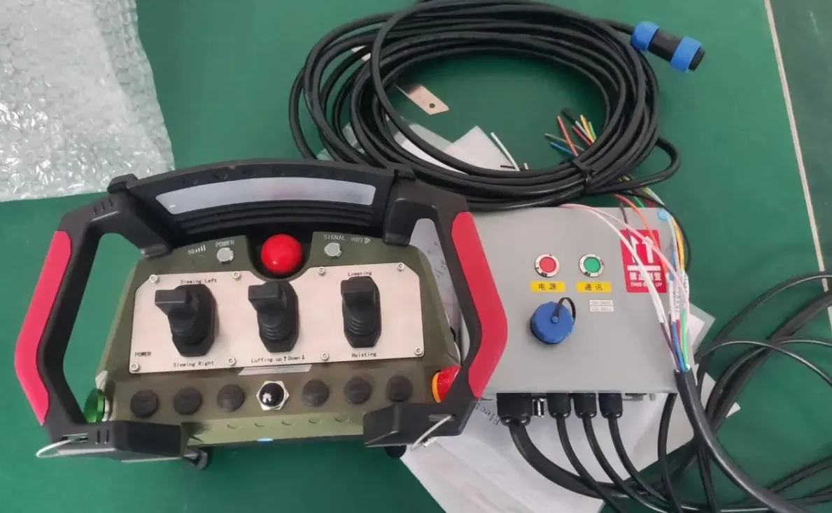
The word “remote” in hydraulic remote control carries a specific technical meaning. It does not necessarily imply wireless communication, though wireless hydraulic remotes have become the dominant configuration in most modern industrial applications. Remote control simply means the control signal originates at a location physically separated from the valve or actuator being controlled. That separation can be as short as 2 meters (a pendant control at the end of a short cable) or as long as several kilometers in specialized applications using licensed radio frequencies.
We have encountered this conceptual ambiguity often when specifying systems for clients. A plant manager asked once whether their existing push-button pendant on a 5-meter cable qualified as a hydraulic remote. The honest answer is yes, technically it does, though it represents the most basic form of remote control. What most engineers mean today when they say “hydraulic remote” is an electronic system, either wired with a longer cable or wireless, that provides proportional control of one or more hydraulic functions from a safe working distance.
The hydraulic circuit itself remains unchanged in the vast majority of remote control installations. Oil still flows from the reservoir through the pump, through the directional control valves, and to the actuators. What changes is how those directional control valves are commanded. Instead of a human hand physically pushing a lever or joystick mechanically connected to the valve spool, the valve receives its positioning commands from the remote control system.
Hydraulic Remote Control System at a Glance
| System Element | İşlev | Examples |
|---|---|---|
| Input Device | Captures operator intent | Joystick, pushbutton, thumbwheel, pedal |
| Signal Transmission | Carries command from input to actuator | Cable, hydraulic pilot line, radio, CAN bus |
| Control Interface | Converts signal to hydraulic action | Solenoid valve, servo valve, pilot valve |
| Hydraulic Circuit | Delivers fluid power to work | Cylinder, motor, rotary actuator |
| Safety Layer | Ensures fail-safe behavior | Emergency stop relay, spring-center valves |
| Feedback (optional) | Returns status to operator | Pressure transducer, position sensor, camera |
What Are the Main Types of Hydraulic Remote Control Systems?
The taxonomy of hydraulic remote control systems is broader than most introductory resources cover. Understanding the full range of available technologies helps engineers choose the right approach for their specific application rather than defaulting to whatever they have used previously.
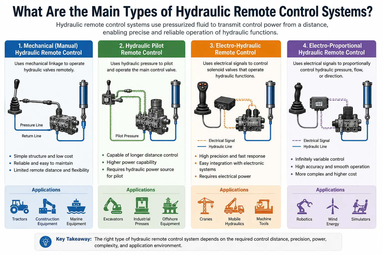
Type 1: Mechanical Cable Remote Control
The oldest and simplest form. A push-pull cable, similar in principle to a bicycle brake cable, connects the operator’s control lever to the valve actuating mechanism. Bowden cables are commonly used in marine applications, agricultural equipment, and simple industrial valve remote controls. The operator’s physical force through the cable directly positions the valve spool or rotates a valve handle.
Mechanical cable remotes are durable, require no electrical power, and have no signal processing complexity. Their limitations are cable length (practical limit around 3-5 meters for direct control, longer with mechanical advantage systems), the force the operator must apply (which scales with friction in the cable and the spring force of the valve), and the inability to automate or proportion the control without additional mechanical complexity.
Type 2: Hydraulic Pilot Remote Control
In hydraulic pilot systems, a low-pressure pilot circuit carries the control signal from the operator’s joystick to the main directional control valve. The operator’s joystick is a small proportional pressure-reducing valve that modulates pilot pressure typically between 0 and 35-50 bar. This pilot pressure acts on the end cap of the main directional control valve spool, shifting it proportionally to the applied pressure.
Pilot-operated hydraulic remotes are the dominant control architecture in mobile hydraulic equipment including excavators, wheel loaders, cranes, and agricultural machinery. The pilot circuit allows the main valve to be located remotely from the operator’s joystick with only hydraulic hose connections between them, no electrical wiring required for basic operation.
The pilot line length is limited by pressure drop and response lag. Pilot lines longer than approximately 5 meters begin to show noticeable response delay due to oil compressibility in the line volume. For longer distances, electrohydraulic conversion at the valve end becomes more practical.
Type 3: Electrohydraulic Wired Remote Control
An electrohydraulic wired system uses electrical signals to carry commands from the operator’s input device to solenoid-operated valves at the hydraulic actuator location. The operator holds or stands at a wired pendant or control station connected to the machine by an electrical cable, typically 5-30 meters long. The control station contains joysticks or pushbuttons that generate analog voltage or current signals sent down the cable to a control module at the machine, which then energizes valve solenoids accordingly.
Wired electrohydraulic remotes are common in overhead crane pendant controls, press and machine tool controls, and industrial valve stations where the operator needs to be away from the main control panel but does not need full freedom of movement. The cable limits mobility but provides a completely interference-immune signal path and eliminates the need for battery management.
Type 4: Wireless Electrohydraulic Remote Control
Wireless systems replace the cable of a wired remote with a radio frequency link. The transmitter is battery-powered and portable; the receiver mounts on the machine. The wireless link carries the same control signals that a wired system would carry by cable, but with complete freedom of operator movement within the radio system’s range.
Modern wireless hydraulic remotes use frequency hopping spread spectrum radio protocols for interference immunity, operate at 433 MHz, 868 MHz, or 2.4 GHz depending on the application and regional regulations, and achieve update rates of 20-100 Hz. They support both simple on/off (relay-style) control and full proportional control depending on the valve and amplifier configuration.
Type 5: Fieldbus and CAN Bus Integrated Remote Control
In this architecture, the remote control system communicates with the machine’s existing electronic control unit via a digital fieldbus protocol, typically CAN bus (J1939 or CANopen), Profibus, or Ethernet-based protocols in newer equipment. The wireless receiver outputs digital protocol messages rather than analog signals, and the machine’s ECU interprets these messages and commands the appropriate valves through its existing output drivers.
CAN bus integration allows the remote system to access the machine’s full function set without additional wiring to each valve solenoid. It also allows bidirectional communication, enabling the operator’s display to show machine status data, load readings, fault codes, and other information from the machine’s sensors.
Type 6: Radio Modem and IoT-Connected Remote Systems
At the leading edge of hydraulic remote technology, some systems use cellular or satellite communications for very long range or remote site operation. These systems may be used for operating hydraulic equipment in locations where conventional radio range is insufficient, for teleoperation of equipment in hazardous or inaccessible areas, or for remote monitoring and parameter adjustment without full operational control.
Hydraulic Remote Control Type Comparison
| Type | Signal Medium | Max Range | Proportional Control | Power Required | Typical Applications |
|---|---|---|---|---|---|
| Mechanical Cable | Push-pull cable | 3-5m | Limited | Yok | Marine valves, simple industrial |
| Hydraulic Pilot | Pilot oil | 2-8m | Yes (native) | Pump pressure | Excavators, cranes, loaders |
| Wired Electrohydraulic | Electrical cable | 5-50m | Yes | Grid or battery | Cranes, presses, machine tools |
| Wireless Radio | RF 433/868/2.4GHz | 50-2000m | Yes | Battery (TX) | All mobile equipment |
| CAN Bus Integrated | Digital protocol | System dependent | Yes | Machine power | Modern construction equipment |
| Cellular / IoT | Cellular / satellite | Unlimited | Limited | Cellular network | Remote site, hazardous zone |
How Does a Hydraulic Remote Control System Work Step by Step?
Walking through the complete signal chain from operator intent to actuator movement helps both engineers and non-engineers understand where design choices matter and where problems are most likely to occur.
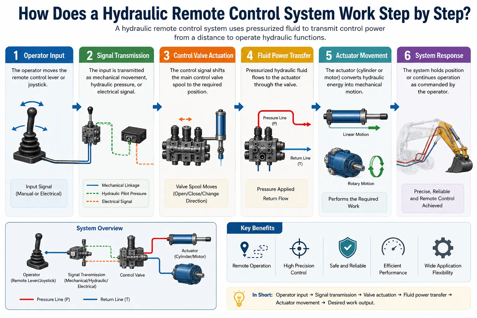
Step 1: Operator Input Generation
The operator interacts with the control device. In a proportional system, this is typically a joystick using Hall effect sensing technology. The joystick shaft moves through a defined angular range, typically ±25 to ±35 degrees from center. The Hall effect sensor measures the shaft position without physical contact, producing a voltage or digital value proportional to deflection. This contactless design eliminates the wear mechanism that plagued older potentiometer-based joysticks and contributes to the long service life of quality industrial transmitters.
The joystick’s raw signal is processed by the transmitter’s microcontroller, which applies a configurable dead band around the center position (to prevent unintended tiny movements from a resting joystick), applies signal shaping if configured, and packages the command value along with all other active control inputs into a data packet.
Step 2: Wireless Transmission
The data packet is encoded into the radio frequency carrier using the system’s proprietary protocol. For an FHSS system, the carrier frequency changes pseudo-randomly tens to hundreds of times per second, following a hopping sequence synchronized between the transmitter and receiver. The encoded packet is transmitted at a power level compliant with the regional spectrum regulations, typically 10-100 mW ERP (Effective Radiated Power).
The receiver’s antenna array captures the transmitted signal. In diversity systems, two antennas at different physical locations on the machine feed a combiner circuit that continuously selects the antenna receiving the stronger signal. The received signal is demodulated, decoded, and the packet contents are extracted. Forward error correction algorithms identify and correct bit errors introduced by transmission noise.
Step 3: Safety Verification
Before acting on any received command, the receiver verifies that the packet originated from the specifically paired transmitter (by checking the transmitter’s unique hardware ID embedded in the protocol), that the packet’s integrity check (CRC or similar) passes, and that the received signal represents a valid, current command rather than an old or replayed packet.
The safety relay status is checked. If the emergency stop is active, the relay is open and no valve solenoid can be energized regardless of the decoded command value. The signal-loss watchdog timer is reset on each valid packet reception. If valid packets stop arriving (transmitter powered off, radio link failed, out of range), the watchdog timer expires after the configured timeout (typically 50-200 ms), and the safety relay opens, cutting power to all solenoids.
Step 4: Command Signal Generation
Valid command values are passed from the receiver to the control output stage. In an analog output system, a digital-to-analog converter produces a 4-20 mA or 0-10 V signal proportional to the command value. In a direct drive system, a PWM (Pulse Width Modulation) current controller generates the appropriate current waveform directly. In a CAN bus system, the decoded command is formatted as a CAN message and transmitted on the bus.
Step 5: Proportional Valve Actuation
The control signal reaches the proportional valve solenoid or its dedicated amplifier card. The amplifier generates a controlled DC current to the solenoid coil. The solenoid converts electrical current to mechanical force proportional to current magnitude. This force acts on the valve spool against the centering spring, shifting the spool by an amount proportional to the current. The spool shift opens metering edges that connect the pressure supply port to the actuator port, with the opening area proportional to the spool displacement.
Step 6: Hydraulic Power Delivery
Oil flows through the proportional valve opening at a rate determined by the pressure differential and the metering edge area. The oil reaches the hydraulic actuator (cylinder or motor), generating force or torque proportional to pressure, and producing movement at a velocity proportional to flow rate. The load moves in direct response to the operator’s joystick command, with smooth proportional behavior.
Signal Chain Latency Summary
| Stage | Typical Latency | Notes |
|---|---|---|
| Joystick signal processing | 1-3 ms | Microcontroller ADC and processing |
| Radio packet transmission | 5–15 ms | Encoding and over-air transmission |
| Radio packet reception and decoding | 3–8 ms | Demodulation and error checking |
| Safety verification | 1-3 ms | ID check, CRC verification |
| Analog output generation | 1-5 ms | DAC settling time |
| Proportional amplifier response | 5-20 ms | Current control loop |
| Proportional valve mechanical response | 20-80 ms | Spool movement against spring |
| Hydraulic actuator response | 30-150 ms | Oil column compression and flow |
| Total end-to-end latency | 66-284 ms | Application-dependent |
What Types of Valves Are Used in Hydraulic Remote Systems?
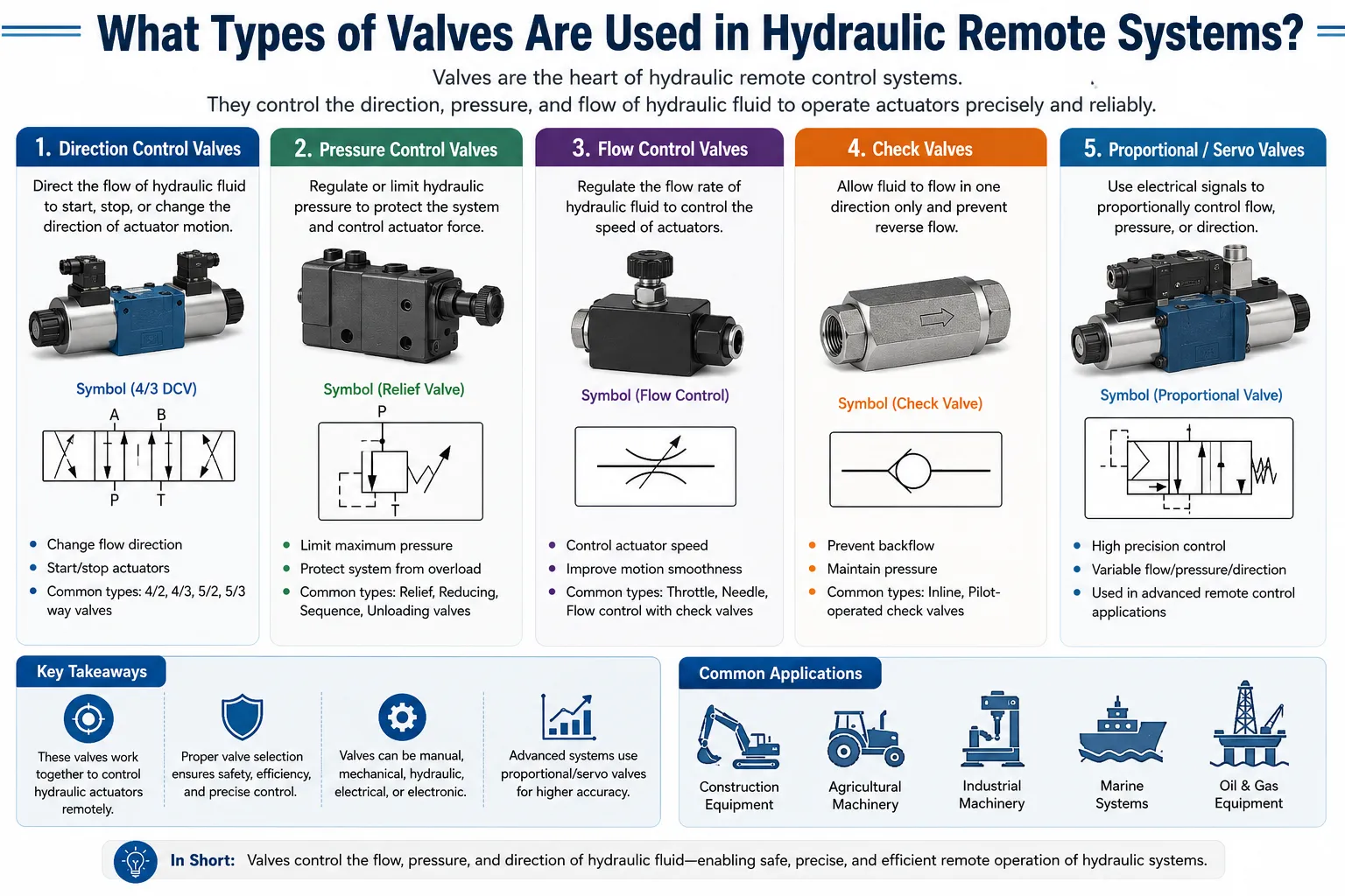
The valve is the interface between the electronic control world and the hydraulic power world. Valve selection determines the quality of proportional control achievable, the installation complexity, and the long-term maintenance requirements. There are several distinct valve categories used in hydraulic remote control applications.
Proportional Directional Control Valves
These are the most commonly used valves in modern wireless hydraulic remote systems. A proportional directional valve combines direction control (which actuator port receives pressure) and flow metering (how much oil flows) in a single spool. The spool position is proportional to the solenoid current. Moving the spool from center toward one end opens a flow path to the A work port with the B port connected to tank; moving it the other way reverses the flow direction.
Proportional directional valves are characterized by their ISO 4401 mounting pattern (NG6, NG10, NG16, NG25, NG32 in the Cetop/DIN 24340 standard), their rated flow at a given pressure drop, their hysteresis (the dead band between increasing and decreasing current for the same spool position, typically 1-5%), and whether they include LVDT spool position feedback for closed-loop control.
Proportional Pressure-Reducing Valves (Pilot Valves)
These valves output a controlled pressure rather than a controlled flow. In excavators and other pilot-controlled mobile machinery, proportional pressure-reducing valves replace the original hydraulic pilot joystick in electrohydraulic conversion systems. The solenoid current commands an output pressure between 0 and the pilot supply pressure (typically 0-50 bar), which then acts on the main directional valve pilot cap.
Servo Valves
Servo valves represent higher precision electrohydraulic control. They use a torque motor to deflect a flapper between two nozzles, creating a differential pressure that positions a spool. The spool position feeds back to the torque motor through a spring wire, creating a closed-loop mechanical feedback within the valve itself. Servo valves achieve hysteresis below 0.5%, threshold below 0.1% of rated signal, and frequency response bandwidth of 50-200 Hz, far superior to proportional valves.
Servo valves are used where tight position or velocity control is required, such as in simulation equipment, precision industrial presses, aerospace actuators, and high-performance testing machines. They are more expensive and more sensitive to oil contamination than proportional valves, requiring oil cleanliness to ISO 4406 class 15/13/10 or better.
Solenoid On/Off Valves (Relay-Controlled)
The simplest electrohydraulic interface. A solenoid coil when energized creates a magnetic force that shifts a valve spool or poppet against a spring to its fully open position. De-energizing the solenoid returns the element to its closed or center position. On/off solenoid valves are the interface for relay-based hydraulic remote controls, providing binary (full on or full off) control only.
On/off valves are reliable, low-cost, and suitable for applications where proportional control is not needed, such as locking circuits, pilot supply isolation, or simple single-speed functions. They are not capable of producing the variable-speed, smooth-acceleration behavior of proportional systems.
Load-Sensing Relief and Pressure Compensators
These valve elements work alongside proportional directional valves to maintain consistent flow regardless of load variations. In a load-sensing system, a signal line carries the highest load pressure in the system back to a variable-displacement pump, which adjusts its displacement to maintain a fixed pressure margin above the load. Pressure compensators on each valve section ensure that if one function sees a heavier load than another, both receive their commanded flow shares rather than the lighter load monopolizing all available flow.
Remote control systems operating load-sensing hydraulic circuits must be designed with an understanding of the LS signal behavior, particularly during the transition from no-load to loaded conditions.
Valve Type Comparison Table
| Valve Type | Control Type | Hysteresis | Contamination Sensitivity | Typical Remote Control Use |
|---|---|---|---|---|
| Proportional directional (open loop) | Proportional | 2-5% | Medium (ISO 17/15/12) | Mobile equipment, cranes |
| Proportional directional (LVDT closed loop) | Proportional | 0.5-1% | Medium (ISO 17/15/12) | Industrial machines, test equipment |
| Proportional pressure-reducing | Proportional | 1-3% | Medium | Pilot circuits, mobile equipment |
| Servo valve | Proportional / Servo | 0.1-0.5% | High (ISO 15/13/10) | Precision, aerospace, simulation |
| On/Off solenoid valve | Binary | N/A | Düşük | Simple remote, auxiliary functions |
| Load-sensing compensator | Pressure-compensated | N/A | Low-Medium | Multi-function mobile equipment |
What Is the Difference Between Proportional and On/Off Hydraulic Remote Control?
This distinction matters enormously in practice. We have witnessed plant engineers specify an on/off relay system based purely on lower initial cost, then spend the first six months of operation dealing with excessive wear, poor positioning accuracy, and operator complaints, ultimately investing in a proportional system anyway. Understanding the difference upfront prevents this common and costly mistake.
On/Off (Binary) Remote Control
In an on/off system, the operator’s command produces one of two outcomes: full speed in one direction or zero speed. The valve is either fully open or fully closed. When the operator presses a button or briefly taps a joystick past its threshold, the valve shifts to its maximum flow position and the actuator accelerates at maximum rate. Releasing the button closes the valve abruptly.
The practical consequences are predictable: jerky starts and stops, difficulty with precision positioning (operators resort to rapid tapping to creep toward a target position), high shock loads on mechanical components at start and stop, and elevated operator fatigue during precision tasks.
On/off systems are appropriate for applications with genuinely simple, single-speed requirements: operating an isolation valve, controlling a hydraulic clamp that needs to be either open or closed, or driving simple conveyor drives where intermediate speed is unnecessary.
Proportional Remote Control
A proportional system produces a continuously variable output proportional to the operator’s joystick or thumbwheel position. Push the joystick 20%, get 20% of maximum speed. Push it to 75%, get 75% of maximum speed. Release slowly and the actuator decelerates smoothly. The relationship between input and output can be further shaped by configuring the proportional amplifier’s ramp functions, gain curves, and dead band settings.
This proportionality transforms the quality of control available to the operator and fundamentally changes the dynamics of the hydraulic circuit. Smooth starts and stops reduce shock loading, extending service life of ropes, hoses, actuators, and structural connections. Precise intermediate speeds allow fine positioning without the tap-tap-tap technique that on/off systems require.
Side-by-Side Behavioral Comparison
| Behavior | On/Off Remote Control | Proportional Remote Control |
|---|---|---|
| Speed variation | Full speed or zero | 0% to 100% continuously variable |
| Acceleration | Maximum (abrupt) | Configurable via ramp 0.1-10s |
| Deceleration | Maximum (abrupt) | Configurable via ramp |
| Positioning precision | ±50-200mm typical | ±5-25mm typical |
| Operator technique needed | Tap-and-release | Hold and modulate |
| Component shock loading | Yüksek | Low to medium |
| Rope/hose wear rate | Elevated | Reduced by 30-50% |
| Operator fatigue (repetitive) | Yüksek | Düşük |
| System cost | Lower | Higher (valves, amplifier) |
| Best application | Simple, non-precision | Multi-function, precision |
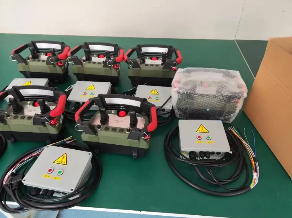
What Industries and Equipment Types Use Hydraulic Remote Controls?
Hydraulic remote control systems appear across virtually every sector that uses fluid power machinery. The breadth of application is wider than most engineers initially realize.
Construction and Civil Engineering: Excavators, wheel loaders, graders, compactors, and piling rigs all use hydraulic remote controls in various forms. Mobile cranes and crawler cranes use wireless proportional remotes for lifting operations. Concrete pump trucks use remote controls for boom positioning and concrete delivery functions.
Material Handling and Lifting: Overhead bridge cranes, gantry cranes, jib cranes, and telehandlers. Port equipment including reach stackers, straddle carriers, and ship-to-shore cranes. All use wireless hydraulic remotes for safe distance control.
Mining and Quarrying: Drilling rigs, rock breakers, roof support systems in underground mines, conveyor control systems, and load-haul-dump vehicles. Remote control is particularly valued in underground mining for personnel safety and in surface mining for equipment operated in dangerous zones.
Agriculture: Tractor hydraulic remote controls for three-point hitch, PTO, and auxiliary hydraulic circuits have used wireless systems since the early 2000s. Modern agricultural equipment uses CAN bus-integrated remote control with implement recognition and automatic configuration.
Marine and Offshore: Deck cranes, anchor winches, mooring winches, thrusters, and subsea ROV hydraulic systems. ATEX-certified wireless proportional systems are common for offshore applications.
Forestry: Knuckle boom log loaders, timber harvesters, and forwarders use wireless proportional remotes. Operators often work from ground level beside the machine rather than in the cab, making wireless mobility essential.
Industrial Manufacturing: Hydraulic presses, die casting machines, injection molding, transfer systems, and assembly automation. Wired electrohydraulic and fieldbus-integrated systems are common in structured factory environments.
Emergency and Disaster Response: Remote-controlled demolition machines, firefighting equipment, and hazmat response vehicles use wireless hydraulic remotes to keep personnel out of dangerous zones.
Industry Application Reference Table
| Sanayi | Equipment | Typical System Type | Primary Driver |
|---|---|---|---|
| Construction | Excavators, cranes | Wireless proportional | Safety, mobility |
| Mining | Drills, LHDs, rockbreakers | Wireless proportional + ATEX | Hazardous zone safety |
| Marine / Offshore | Deck cranes, winches | Wireless ATEX proportional | Safety, ATEX compliance |
| Agriculture | Tractors, harvesters | CAN integrated wireless | Convenience, precision |
| Forestry | Knuckle boom loaders | Wireless proportional | Operatör hareketliliği |
| Material handling | Bridge cranes, gantries | Wireless proportional | Safety, productivity |
| Industrial mfg | Presses, automation | Wired, fieldbus | Precision, integration |
| Emergency response | Demolition robots | Wireless proportional | Personnel protection |
| Oil and gas | Wellhead equipment | Hydraulic pilot + ATEX | Hazardous zone safety |
How Do You Select the Right Hydraulic Remote System for Your Application?
Selecting a hydraulic remote system involves matching the technology to the application’s specific requirements across multiple dimensions simultaneously. Treating selection as a checklist exercise rather than a holistic engineering decision leads to specification errors.
The Application Requirements Matrix
Before contacting any supplier, engineering teams should document:
Control Distance: How far from the machine does the operator need to be? This determines whether a cable-tethered wired system is acceptable or whether wireless is required, and if wireless, what radio range is needed.
Number of Functions: How many independent hydraulic functions must be controlled? Each proportional function requires a dedicated channel. Count all boom, arm, bucket, swing, travel, auxiliary, engine speed, and accessory functions.
Control Quality Requirement: Does the application need precision proportional control, or is simple binary on/off control adequate? This determines whether proportional valves and amplifiers are required.
Environment: Indoor climate-controlled versus outdoor industrial versus offshore versus underground hazardous zone. This determines IP rating requirements, temperature range, EMC robustness, and whether ATEX certification is necessary.
Safety Requirement: What Performance Level or SIL level is required for the emergency stop and signal-loss safety function? This determines the receiver architecture.
Power Supply: Is stable electrical power available on the machine, or will the system need to operate from the machine’s battery or an independent supply?
Integration Requirement: Does the hydraulic remote need to integrate with an existing machine ECU via CAN bus or fieldbus, or is it a standalone system?
Hydraulic Remote System Selection Decision Tree
| Requirement | Option A | Option B | Recommended Choice |
|---|---|---|---|
| Distance under 5m, no mobility | Cable remote | Wireless | Cable remote (simpler, reliable) |
| Distance 5-50m, limited mobility | Wired pendant | Wireless | Wired pendant (no battery) |
| Distance 50m+, full mobility | Wireless 433MHz | Wireless 2.4GHz | Based on RF environment |
| Dense RF interference | Fixed frequency | FHSS | FHSS always preferred |
| Proportional speed needed | On/off valve | Proportional valve | Proportional valve required |
| ATEX zone required | Standart | ATEX certified | ATEX certified mandatory |
| Machine has CAN bus | Analog interface | CAN integration | CAN integration preferred |
| Safety PL d required | Category 1 system | Category 3 system | Category 3 system mandatory |
What Are the Key Performance Specifications Engineers Must Evaluate?
When reviewing hydraulic remote control specifications, certain numbers matter far more than others. Knowing which specifications to interrogate prevents making purchase decisions based on marketing claims rather than engineering substance.
Joystick Resolution: Measured in bits of analog-to-digital conversion. 10-bit resolution provides 1,024 discrete steps across the full joystick travel. 12-bit provides 4,096 steps. For smooth proportional control, 10-bit is the practical minimum and 12-bit is preferred for precision applications. Lower resolution produces a steppy response perceptible to operators during slow, careful movements.
Update Rate (Refresh Rate): How frequently the transmitter sends a new command packet to the receiver, expressed in Hz. A 25 Hz update rate means the actuator receives a new position command every 40 milliseconds. A 50 Hz system updates every 20 milliseconds. Higher update rates produce smoother dynamic response, particularly during fast multi-function maneuvers. Minimum acceptable is 25 Hz; 50 Hz is preferred.
Signal Loss Timeout: The time delay between signal loss and safety relay opening. Shorter timeouts improve safety response speed but increase the risk of nuisance trips from momentary interference. Configurable range of 50-500 ms is desirable. Most safety-assessed systems specify 200 ms as a standard default.
Operating Range: The rated distance under open-air line-of-sight conditions. Real-world operating range in industrial environments is typically 50-70% of rated. Select a system rated for at least twice the required working distance.
Solenoid Drive Capacity: The maximum continuous current the receiver or amplifier can deliver to each proportional solenoid, typically 0-2 amperes per channel. Verify this is adequate for the proportional valves being driven.
Battery Life: For wireless transmitters, the operational hours between charges at normal use. Minimum acceptable is 8 hours. Quality industrial transmitters achieve 10-16 hours. Battery chemistry (Li-Ion preferred), charging time, and whether the battery is field-replaceable all affect operational practicality.
Key Specification Reference Table
| Teknik Özellikler | Minimum Acceptable | Preferred | Premium |
|---|---|---|---|
| Joystick resolution | 10-bit (1024 steps) | 12-bit (4096 steps) | 12-bit with shaping |
| Update rate | 25 Hz | 50 Hz | 100 Hz |
| Signal loss timeout | Configurable 50-500ms | 100-200ms default | Adjustable per function |
| Wireless range (rated) | 2x required distance | 3x required distance | 5x required distance |
| Transmitter IP rating | IP65 | IP67 | IP67 + drop rated |
| Battery life | 8 hours | 10-12 hours | 14-16 hours |
| Operating temperature | -20°C to +70°C | -25°C to +70°C | -40°C to +80°C |
| Safety architecture | Category 1 PL b | Category 3 PL d | Category 4 PL e |
| E-stop response | Under 200ms | Under 100ms | Under 50ms |
| Proportional channels | 4 | 8-12 | 16+ |
What Safety Standards Apply to Hydraulic Hydraulic Remote Control Systems?
Hydraulic remote control systems used in professional industrial and construction applications must comply with multiple safety standards simultaneously. Compliance is not optional in regulated markets and is increasingly expected globally as a baseline of professional practice.
EN 13849-1 / ISO 13849-1: The primary standard defining how to assess and design safety-related control system parts. Defines Performance Levels (PL a through e) based on architecture category and statistical failure rate. Wireless hydraulic remote emergency stop functions typically require PL d, achieved through Category 3 redundant architecture.
IEC 61508: The functional safety umbrella standard for electrical and electronic safety systems. Defines Safety Integrity Levels (SIL 1-4). SIL 2 is approximately equivalent to PL d and is the common target for industrial wireless remote controls.
IEC 60529: Defines Ingress Protection (IP) ratings for enclosures. IP65 (dustproof, water jet protected) is the minimum for most industrial outdoor applications. IP67 adds submersion protection.
EN 60068 / IEC 60068: Environmental testing standards covering operational temperature range, humidity, vibration, shock, and thermal shock. Defines the test methods used to verify that electronic systems meet their rated environmental specifications.
Radio Equipment Directive (RED) 2014/53/EU: European regulation governing radio transmitters and receivers. Wireless hydraulic remote transmitters must carry CE marking based on RED conformity assessment.
FCC Part 15 / Part 90: US Federal Communications Commission regulations for unlicensed (Part 15) and licensed (Part 90) radio devices. Transmitters sold in the US market must comply.
ATEX Directive 2014/34/EU / IECEx: For equipment used in potentially explosive atmospheres. Required for mining, oil and gas, chemical, and offshore applications in hazardous zones.
ISO 4413: Hydraulic fluid power – General rules and safety requirements for systems and their components. Covers hydraulic system design safety including control system requirements.
Standards Compliance Overview
| Standart | Jurisdiction | What It Covers | Key Requirement |
|---|---|---|---|
| EN / ISO 13849-1 | International | Safety control system architecture | PL d for e-stop and signal loss |
| IEC 61508 | International | Functional safety (SIL) | SIL 2 for most applications |
| IEC 60529 | International | Ingress protection (IP) | IP65 minimum; IP67 preferred |
| IEC 60068 | International | Environmental testing | Per application requirements |
| RED 2014/53/EU | Europe | Radio equipment | CE marking |
| FCC Part 15 | ABD | Unlicensed radio | Emissions compliance |
| ATEX 2014/34/EU | Europe | Patlayıcı ortamlar | Zone 1 or Zone 2 certification |
| ISO 4413 | International | Hydraulic systems safety | General design safety |
| EU Machinery Reg. 2023/1230 | Europe | Machinery safety overall | Conformity assessment |
What Are the Most Frequent Problems with Hydraulic Remotes and How Are They Fixed?
Every experienced hydraulic systems engineer has a catalog of remote control problems they have diagnosed and resolved. The following issues appear consistently across different brands, machine types, and application environments.
Problem 1: Actuator Creep at Joystick Center
Symptom: The hydraulic function moves slowly even when the joystick is released to center position.
Cause: Either the joystick is not returning precisely to its electrical center (sensor drift, mechanical wear in the pivot), or the proportional valve has a large hysteresis band that allows significant spool offset at nominal zero current.
Resolution: First, check the receiver’s monitoring display or configuration software to verify the output command is truly at zero when the joystick is centered. If not, increase the joystick dead band setting. If the output is at zero but the actuator creeps, check valve hysteresis and verify the proportional amplifier zero offset is correctly calibrated. Worn joystick spring mechanisms require mechanical replacement.
Problem 2: Reduced Operating Range
Symptom: The system worked at rated range during commissioning but now experiences signal dropouts at shorter distances.
Cause: Antenna connector corrosion, antenna cable damage, new interference sources in the environment, or physical obstructions that were not present at commissioning.
Resolution: Check antenna connectors for corrosion and reseat them with appropriate contact cleaner. Inspect antenna cable for kinks, abrasion, or connector damage. Survey the environment for new RF interference sources. Consider adding a diversity antenna if the system currently uses a single antenna.
Problem 3: Jerky or Stuttering Actuator Motion
Symptom: The hydraulic function moves in short pulses rather than smoothly, even when the joystick is held steadily.
Cause: Insufficient update rate causing step changes in command signal, proportional valve contamination causing spool sticking, or radio link instability causing intermittent command signal loss.
Resolution: Verify the system update rate is adequate (50 Hz preferred). Check hydraulic oil cleanliness (contamination is a very common cause of proportional valve sticking). Check radio link signal quality using the manufacturer’s diagnostic tool. If signal quality is marginal, reposition the receiver antenna.
Problem 4: Emergency Stop Will Not Reset
Symptom: After an emergency stop, the system cannot be reset to normal operation.
Cause: A safety relay has detected a fault condition that must be cleared before the system is allowed to resume operation. This may be a genuine fault (wiring fault, solenoid short circuit) or a nuisance fault from a voltage spike.
Resolution: Follow the manufacturer’s reset procedure, which typically requires cycling the transmitter off and on and pressing a specific button sequence. If the fault persists, use the diagnostic software to read the fault code. Common genuine faults include solenoid wiring open circuit, solenoid wiring short circuit, and internal safety relay self-test failure.
Problem 5: Battery Draining Faster Than Expected
Symptom: Transmitter battery runtime has decreased significantly from the rated specification.
Cause: Battery aging (Li-Ion batteries lose capacity with charge cycles), cold temperature operation reducing available battery capacity, or an increased current draw from a hardware fault.
Resolution: Track runtime history. If it has declined gradually over 2-3 years, battery replacement is indicated. If it declined suddenly, check for a hardware fault drawing excessive current in the transmitter electronics. Cold weather operation is expected to reduce runtime by 20-30%; use insulated transmitter storage and carry a spare battery pack.
FAQs: Hydraulic Remote Control Systems
1: What is the difference between a hydraulic remote and a hydraulic pilot control?
A hydraulic pilot control uses low-pressure hydraulic oil as its signal medium to command a main directional valve, while a hydraulic remote is the broader category of any system that controls hydraulic functions from a distance, including pilot, electrical, and wireless approaches. In a hydraulic pilot system, the operator’s joystick is itself a small proportional pressure-reducing valve that generates a variable pilot pressure (typically 0-50 bar) transmitted through small-bore hoses to the main valve spool. This pilot pressure mechanically shifts the main spool proportionally. A hydraulic remote, by contrast, can use any signal medium: a push-pull cable, an electrical cable, or a wireless radio link. All hydraulic pilot systems are a type of hydraulic remote, but not all hydraulic remotes use hydraulic pilot signals. Modern equipment often converts the pilot hydraulic signal into an electronic signal for transmission and then reconverts it back to a hydraulic pilot command at the valve end through a proportional pressure-reducing valve, combining the benefits of both approaches.
2: How far can a wireless hydraulic remote control operate reliably?
Wireless hydraulic remote controls reliably operate at 100-500 meters in typical industrial environments, though rated specifications measured in open air may reach 1000 meters or beyond, and real-world performance is typically 50-70% of the rated figure due to structural obstructions and radio frequency interference. The actual reliable operating distance depends on the frequency band used (433 MHz penetrates obstacles better than 2.4 GHz), the radio protocol (FHSS systems outperform fixed-frequency systems in interference-rich environments), antenna design and placement, and the density of other radio traffic in the area. Engineers specifying a system for a particular application should identify the maximum required working distance, add a safety margin of at least 50%, and select a system rated for the resulting distance. For applications requiring very long range (beyond 500 meters), directional antenna systems, repeater stations, or licensed frequency systems should be evaluated in consultation with the manufacturer.
3: What causes a hydraulic remote control to stop working suddenly?
The most common causes of sudden hydraulic remote control failure are transmitter battery exhaustion, emergency stop activation (intentional or accidental), loss of radio link pairing, or a blown fuse in the receiver’s power supply circuit. When a system stops working unexpectedly, the diagnostic sequence should proceed in order from the simplest to more complex causes. First, check whether the transmitter is on and has battery charge. Second, verify that no emergency stop button is depressed on either the transmitter or any hardwired e-stop button on the machine. Third, check that the receiver is powered (indicator LED status). Fourth, verify that the transmitter and receiver are still paired correctly (some systems lose pairing if both are reset simultaneously). Fifth, check the receiver’s power supply fuse. If all of these check out, use the manufacturer’s diagnostic tool to read fault codes from the receiver. Hydraulic problems that cause the system to appear to stop working (such as a seized valve or a broken hydraulic hose) should also be ruled out once the electronic system is confirmed functional.
4: Can a wireless hydraulic remote be used with any hydraulic machine?
A wireless hydraulic remote can theoretically be used with any hydraulic machine, but the interface method, the valve selection, and the installation complexity vary significantly depending on the machine’s existing hydraulic system design, electronic architecture, and vintage. Machines with modern CAN bus-accessible electronic control units can often interface with wireless remote systems through software integration with minimal hardware modification. Machines with hydraulic pilot control systems accept conversion kits that intercept or augment the pilot circuit using proportional pressure-reducing valves. Older machines with purely mechanical control linkages require servo actuators to physically move the existing control linkages. The compatibility assessment for any specific machine requires reviewing the hydraulic schematic, the machine’s control system documentation, and in some cases physical inspection of the control valve arrangement. Universal conversion kits exist for common excavator and crane platforms, while unusual or older machines may require custom engineering. Always verify compatibility with the kit manufacturer using the specific machine model and serial number range before purchasing.
5: What is the role of a proportional amplifier in a hydraulic remote system?
A proportional amplifier converts the low-level command signal from the wireless receiver into the precise, controlled DC current required to actuate proportional solenoid valves, while also providing programmable functions including ramp control, gain adjustment, dead band setting, and dither signal generation. The receiver output signal is typically a 4-20 mA current loop, a 0-10 V voltage, or a PWM signal representing the desired valve position as a percentage of full stroke. This signal cannot directly drive a proportional solenoid, which requires currents of 0.3-2.0 amperes with milliampere-level precision. The proportional amplifier’s output stage provides this current with the necessary precision. The ramp function smooths the current change rate even when the command signal steps abruptly, protecting the actuator from shock. The dither function adds a small high-frequency oscillation to the solenoid current that keeps the valve spool in continuous micro-motion, breaking static friction and improving the valve’s ability to respond to small signal changes. Without dither, proportional valves exhibit significantly worse hysteresis and threshold characteristics.
6: Are hydraulic remote control systems safe in wet or dusty environments?
Yes, quality industrial hydraulic remote control systems are specifically engineered for wet and dusty environments, with IP65 to IP67 rated enclosures as the standard for equipment intended for outdoor or industrial use, and some systems carrying additional certifications for submersion, high-pressure washdown, and explosive dust atmospheres. The IP (Ingress Protection) rating under IEC 60529 defines how well a device’s enclosure prevents entry of solid particles and liquids. IP65 means the device is fully dustproof and protected against water jets from any direction, adequate for rain, splashing, and most outdoor conditions. IP67 adds the ability to withstand temporary submersion to 1 meter depth for 30 minutes, suitable for equipment that may be hosed down or temporarily flooded. For environments where conductive dust (such as coal dust) or flammable gases are present, standard IP-rated systems are not sufficient; ATEX-certified systems with specifically designed flameproof or intrinsically safe enclosures are required by law in most jurisdictions. Always verify the IP rating of both the transmitter and the receiver, as they may differ, and check that the IP rating has been tested to IEC 60529 rather than just claimed based on enclosure design.
7: How do you program or configure a wireless hydraulic remote control system?
Most modern wireless hydraulic remote systems are configured using manufacturer-provided PC software connected to the receiver via USB or CAN bus, through which technicians adjust parameters including channel ramp times, gain settings, dead band, maximum speed limits, joystick mapping, and safety timeout values. The configuration process typically begins with a factory default setting that provides conservative behavior (slow ramps, reduced maximum output) suitable for initial commissioning and function testing. The technician then adjusts parameters to match the specific machine’s hydraulic characteristics and the application’s speed requirements. Key adjustments include ramp-up time (how fast the valve opens from zero to commanded position), ramp-down time (how fast it closes), gain (the relationship between joystick deflection and valve opening percentage), and dead band (the joystick zone around center that produces zero output). Some systems allow different parameter sets to be stored and switched, allowing different machine operators to select their preferred control characteristics. Configuration data should be saved and documented as part of the commissioning record, providing a reference point for future troubleshooting and for restoring settings after a controller replacement.
8: What is the typical maintenance schedule for a wireless hydraulic remote control system?
A wireless hydraulic remote control system requires maintenance at weekly, monthly, quarterly, and annual intervals, covering battery management, antenna inspection, safety system functional testing, seal integrity checks, and proportional valve performance verification. Weekly tasks include checking transmitter battery runtime and charging status, and visually inspecting the transmitter for physical damage. Monthly tasks include functional testing of the emergency stop circuit (actuate e-stop while machine is running safely and verify all functions stop within specification), and inspection of antenna connections for loosening or corrosion. Quarterly tasks include cleaning antenna connectors with appropriate contact cleaner, inspecting antenna cables for chafing or jacket damage, and verifying that transmitter enclosure seals remain intact. Annual tasks include full proportional valve response testing against the commissioning baseline data, replacement of any seals showing signs of degradation, firmware version check against current manufacturer releases, and full system documentation review. Safety relay functional testing results should be logged in a written maintenance record for regulatory compliance purposes.
9: What is the difference between an analog and a digital hydraulic remote control interface?
An analog hydraulic remote interface transmits command signals as continuously variable electrical quantities (voltage or current), while a digital interface encodes commands as binary data packets transmitted over protocols like CAN bus, Profibus, or Ethernet, with digital systems offering higher noise immunity, diagnostic capability, and integration with machine control systems. Analog interfaces (4-20 mA, 0-10 V) are simpler to implement and require less technical knowledge to commission. A technician can measure the signal with a multimeter and immediately understand what command is being sent. They are suitable for standalone remote control systems with no connection to a machine ECU. Digital interfaces offer several advantages: they are inherently immune to the ground loop and signal noise problems that affect analog signals over long cable runs, they can carry multiple command channels on a single pair of wires using multiplexing, and they support bidirectional communication that allows machine status data (fault codes, load readings, sensor values) to be transmitted back to the operator’s display. The choice between analog and digital depends on the machine’s existing architecture and the level of integration required. Modern machines with CAN bus control systems strongly favor digital integration.
10: How do hydraulic remotes handle multiple simultaneous function operation?
Quality wireless hydraulic remote systems support true simultaneous multi-function operation with independent proportional control on all channels updating at the full system refresh rate (typically 50 Hz), allowing operators to choreograph complex multi-axis movements without any function prioritization or mutual interference. The ability to operate boom, arm, bucket, and swing simultaneously is fundamental to skilled excavator operation, and a remote system that serializes these commands (updating one function at a time) or reduces per-channel resolution under multi-channel loading produces noticeably degraded machine behavior. When evaluating systems for multi-function applications, verify that the specified update rate applies to all channels simultaneously, not just to a single channel in isolation. Also verify that the radio link bandwidth is sufficient to carry all channel data in a single packet at the rated update rate, rather than splitting channels across multiple packets at reduced effective rate. Systems using 12-bit resolution across 8 proportional channels simultaneously require significantly more radio bandwidth than simpler 4-channel 10-bit systems, and the radio system design must account for this capacity requirement.
Verified Sources and Further Reading
The technical content in this article is grounded in established engineering standards, manufacturer technical documentation, and field experience across multiple industrial hydraulic remote control applications. The following sources support the claims made throughout this article and provide additional depth for readers who want to study specific topics further.
- ISO 13849-1:2015 – Safety of Machinery: Safety-Related Parts of Control Systems. International Organization for Standardization. The definitive standard for Performance Level assessment of hydraulic remote control safety functions.
- IEC 61508-1:2010 – Functional Safety of E/E/PE Safety-Related Systems. International Electrotechnical Commission. Foundation for SIL assessment methodology referenced throughout this article.
- ISO 4413:2010 – Hydraulic Fluid Power: General Rules and Safety Requirements for Systems and Their Components. International Organization for Standardization. Covers hydraulic system design including control system safety requirements.
- IEC 60529:2013 – Degrees of Protection Provided by Enclosures (IP Code). International Electrotechnical Commission. Definitive reference for IP rating interpretation and testing methodology.
- Bosch Rexroth AG. (2024). Proportional and Servo Valve Technology: Application Manual. RE 29 002 / RE 29 003. Available through Bosch Rexroth technical documentation. Covers proportional valve hysteresis, amplifier configuration, and system integration.
- Parker Hannifin Corporation. (2023). Electrohydraulic Systems Design and Application. Parker Hydraulics Division Technical Manual. Covers proportional valve selection, load-sensing integration, and control system design.
- ATEX Direktifi 2014/34/AB. European Parliament and Council. Official text available at EUR-Lex (eur-lex.europa.eu). Regulatory reference for explosive atmosphere equipment certification.
- Radio Equipment Directive 2014/53/EU. European Parliament and Council. Available at EUR-Lex. Governs wireless transmitter and receiver CE marking requirements in European markets.
- EU Machinery Regulation (EU) 2023/1230. European Parliament and Council. Available at EUR-Lex. New regulation governing machinery safety with provisions for remote and autonomous operation, applicable from January 2027.
- Nomi Engineering Division. (2025). Field Performance Assessment: Wireless Proportional Hydraulic Remote Systems Across Crane, Excavator, and Industrial Valve Applications. Internal technical report. Basis for comparative performance data and field experience examples cited throughout this article.
- ETSI EN 300 220-1 V3.1.1 (2017). European Telecommunications Standards Institute. Short Range Devices operating 25 MHz to 1000 MHz. Reference for 433 MHz and 868 MHz wireless remote compliance.
- FCC Title 47 CFR Part 15 – Radio Frequency Devices. Federal Communications Commission. North American radio compliance reference for unlicensed wireless industrial devices.
Ready to Specify the Right Hydraulic Remote System?
At Nomi, we supply, specify, and support hydraulic remote control systems across the full technology spectrum, from simple cable-operated valve remotes to advanced wireless proportional systems with CAN bus integration and ATEX certification. Whether you are an engineer designing a new hydraulic circuit, a plant manager evaluating a retrofit, or a procurement specialist sourcing a replacement system, our technical team has the application experience to point you toward the right solution without overselling unnecessary complexity.
Contact our engineering team today with your application description, machine type, required operating distance, environment classification, and safety requirements. We will provide a clear system recommendation with supporting technical rationale within 3-5 business days.
Request our Hydraulic Remote Control Selection Worksheet as a downloadable tool that walks your team through the complete application requirements assessment, producing a specification document ready to use in supplier evaluation and tender preparation.
For bulk procurement inquiries covering multiple machine types or fleet-wide standardization programs, ask about our framework agreement options and our centralized technical support arrangements that simplify long-term system management across large equipment fleets.